
Trim Indicator
This indicator does not need to be converted. This comes from MSN 19521 Air France F-BLCG (my mother was a flight attendant on AF 707s!) that ended its life in Bratislava after a write off. It was repainted in grey but is otherwise untouched. It can easily be interfaced as it is a simple coil gauge. Maximum voltage for all indicators is 1,1V for a full deflection. By changing polarity the indicator can be moved to both sides. Pinout is as follows:
Pin A : RUDDER max deflection voltage 1,2V
Pin B : RUDDER max deflection voltage 1,2V
Pin C : AILERONS max deflection voltage 1,1V
Pin D : AILERONS max deflection voltage 1,1V
Pin E : ELEVATOR max deflection voltage 1,1V
Pin F : ELEVATOR max deflection voltage 1,1V
Pin G N/A
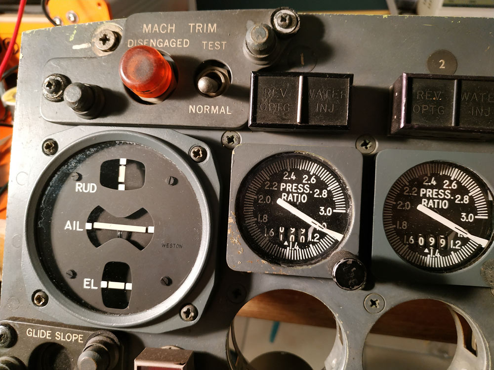
Gauge Description
This indicator is on the pilots’ center panel and contains three windows: Two of these windows, marked AIL and EL respectively, display the trim condition existing in the roll and pitch axis
of the airplane. Each indication represents the result of the voltmeter reading across the respective autopilot servomotor . Deflection of the indicators represent the position of t he Aileron or
Elevator respectively, therefore, the servomotor is rotating or holding against a force (system engaged). The third window is marked RUD. This window displays the trim condition of the rudder as introduced through the linear position transducer of the yaw damper. Deflection of the indicator represents the position of the rudder.
NOTE: Engage yaw damper and Al p only, when the respective indications are zero!