
The attitude warning system provides means of alerting the pilots to an extreme nose -high take-off attitude or to a flight condition approaching a stall. When the system is armed and a near stall attitude is sensed, a shaking device on the captain’s column simulates a buffet condition and makes the control column shake. The attitude warning system components are as follows, a lift transducer with its vane one on each wing, a flap potentiometer mounted on the flap control valves in the main wheel wells, a pair of summing units, a control column shaker
motor and test switches on the overhead panel. The left main landing gear oleo operated (squat) switch, and No.3 throttle operated switch are used to arm the attitude warning system and to control power for anti-icing and system testing.
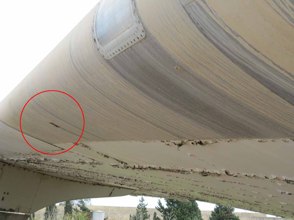
The lift transducers consist of a vane which is spring-loaded to a central position. It is mounted on the lower wing surface near the leading edge of each wing between the inboard engine and the fuselage. The lift transducers sense the airflow pattern in the vicinity of the stagnation point and respond to the movement.at that point.
The system is armed automatically on the ground with advancement of No 3 throttle to the take-off position, or in the air by the left-hand main gear oleo is operated (squat) switch. The system is anti-iced on the ground with the No. 3 throttle retarded, oleo operated switch closed and the respective PITOT/ ATT WARN HEAT switch on the overhead panel in the ON position. The lift transducer a convert air pressure into electrical signals in relation to the airplane stall condition. The transducer signal must be modified for variation in flap position since critical attitude is a function of flap setting as well as stagnation point location on the wing; there are signals from flap position potentiometers are summed with the transducer signals in the summing unit. A strong enough signal sum produced in either unit will energize its summing relay. A signal through either summing unit will energize the left-hand shaker relay and cause the pilot’s control column to shake.
Overrotation in takeoff or approaching the stall speed during flight causes attitude warning, coming under notice by the stickshaker.
The stickshaker is mounted on the pilot’s control column.
Other components of this system are:
- Two lift transducers, one on each wing. A vane is displaced by the airstream. The airstream is affected by the angle of attack. The lift transducers convert air pressure into electrical signals in relation to the airplane stall condition.
- Two flap position potentiometers, one mounted on the inboard flap control valve, the other on the outboard flap control valve. The transducer signal is modified for variation of flap position, since critical attitude is a function of flap setting as well as stagnation point location
- Two summing units, located in the lower 41 compartment. Here the transducer- and flap position potentiometer signals are summed and amplified. A strong enough signal sum produced
in either unit will energize the shaker relay and cause the pilot’s control column to shake. - The attitude warning test system. With the attitude warning test switch, a ground connection causes an unbalance in the respective summing unit. By that an output signal from the amplifier exists. At the same time the oleo bypass switch must be actuated, so the command relay releases and the stick shaker relay will close. For an effective check the flaps must be extended to at least 14°.