
The hydraulic power system consists of an utility hydraulic system and an auxiliary hydraulic system. These systems are independent and are designed to operate with a pressure of 3025 psi. Hydraulic pressure is normally supplied to all units of the utility system by two engine-driven hydraulic pumps, one on each inboard engine. Hydraulic pressure is normally supplied to the units of the auxiliary system by two AC electrically driven pumps. Interconnect valves are provided to allow ground checking of the utility system without engine operation and emergency operation of the wheel brakes from the auxiliary system. The utility hydraulic reservoir and the No 1 auxiliary hydraulic reservoir are in the left wheel well fillet area. 707B the N02 auxiliary hydraulic reservoir is in the right wheel well fillet area.
When the interconnect valves are closed loss of fluid from one system will leave the other system operational. High pressure bleed air from the inboard engines maintains an air pressure of 40 to 45 psi on all reservoirs, pumps supply lines, and system return lines. Aerosafe 2300 W, Skydrol 500 B and Hyjet W hydraulic fluids are used in the system. Warning lights are provided for hydraulic system low pressure and indicators are provided for utility system, broke, and rudder pressure, and for utility reservoir quantity. System capacity is about 707A: 30 gallons, 707B: 32 gallons (ca. 121 l), 707C: 35 gallons (ca. 132 l). With exception to the engine driven hydraulic pump depressurization valves all valves in the hydraulically operated systems are electric mot
or driven valves. If electric power to a valve motor is lost or the CB pulled, the valve will remain in the last selected position and the associated system will remain in the last selected condition.
UTILITY HYDRAULIC SYSTEM
The utility hydraulic system consists of a reservoir, two engine-driven hydraulic pumps, accumulators, switches, lights, gauges, and related valves to operate the system. The system furnishes hydraulic fluid under pressure to operate the
- outboard spoilers,
- the trailing edge
- leading edge flaps
- nose wheel steering
- landing gear
- wheel brakes (707B / 707C and to pressurize the main landing gear truck leveling cylinders).
Return fluid from these systems is routed back to the utility reservoir through a two stage return filter except the return fluid of the broke system which is routed. A utility system relief valve will relieve at 3500 psi and reset at 3150 psi. A bypass valve is provided to assist in maintenance bleeding of the system. The hydraulic fluid and utility pumps are cooled by tubing loops with flow restrictors in the wings.
Approximately 2 gallons (7.57 liters) per minute of hydraulic fluid circulates continuously through these loops.
UTILITY HYDRAULIC RESERVOIR
A 5,4 U.S. gallon capacity reservoir is provided for the utility system . The utility reservoir is serviced through a filler port. Incorporated in the utility reservoir is a sight gauge and a float operated fluid quantity transmitter . The transmitter is electrically connected to a fluid quantity indicator on the F/E’s lower panel. The auxiliary reservoir outlet port on the utility reservoir is located at the 3,2 gallon (ca. 121 l) level. Thus, a minimum of 3,2 gallons (ca. 121 l) remains for the utility system if the
auxiliary system looses fluid.
NOTE: In case of auxiliary system leakage the fluid quantity ind can indicate also in the range between 3,0 and 3,3 gallons remaining fluid. The indication depends on airplane attitude.
Loss of fluid from the utility system will not affect the fluid level in the auxiliary reservoir{s). When the system is in operation (one or both inboard engines operating) all reservoirs, pump
supply lines and system return lines will be pressurized by high pressure air (N2) bleed from the inboard engines into the utility reservoir to insure a positive flow of fluid to the pumps. This pressure will be maintained constant at 40 to 45 psi by an air pressure regulator. The reservoir filler cap must be secured to pressurize the reservoir; unscrewing the cop the first three turns
depressurizes the reservoir. The utility reservoir is located in the left wheel well fillet area.
UTILITY SYSTEM HYDRAULIC PUMPS
These engine-driven pumps are constant pressure variable displacement type pumps delivering up to 22 gallons (ca. 83 l) per minute per pump at take-off rpm and approximately 13 gallons (ca. 49 l) per minute at idle rpm. Output is a function of system demand up to the limit of maximum pump flow rate. The pumps are cooled and lubricated by hydraulic fluid. With the engine windmilling at approach speed the maximum output is approximately 2 gallons (7.57 l) per minute, sufficient for normal operation of spoilers and for reduced rate operation of flaps and landing gear. Pump output can be blocked by
means of two switches.
AUXILIARY HYDRAULIC SYSTEM
The system provides hydraulic fluid under pressure to operate
- the inboard spoilers
- the rudder boost,
- 707C (Cargo): the main cargo door
The No 1 auxiliary hydraulic pump supplies hydraulic fluid to the entire auxiliary system and the system and brake interconnect valves. The No 2 auxiliary hydraulic pump supplies only the rudder
boost and the brake interconnect valve. Each pump is provided with a pressure switch which actuates its law pressure warning light when the pump out put pressure is low. An auxiliary system relief valve will relieve at 3500 psi and reset at 3 150 psi.
AUXILIARY HYDRAULIC RESERVOIR
The 1.4 gallon (5.3 liters) No 1 auxiliary reservoir, located in the left wheel well fillet area is filled from the utility reservoir by a connecting line a t the utility reservoir 3 gallon (11.36 l) level. The auxiliary system cannot deplete the utility reservoir supply of fluid and loss of fluid from the utility system will not affect the level in the auxiliary reservoir.
The auxiliary reservoir supplies both the No 1 and the No 2 auxiliary pump. The No 1 aux pump pressurizes the inboard spoilers and the rudder system while the No 2 aux pump pressurizes only the rudder system. Return fluid from the inboard spoilers and the rudder system discharges in to the aux reservoir.
707B & C: The No 1 aux reservoir supplies both the No 1 aux pump and the No 2 aux reservoir, which incorporates an airbleed fitting for system servicing. The 1,4 gall on No .2 aux reservoir, located in the right-hand wheel well area, feeds the No 2 aux pump to pressurize the rudder system return fluid from the rudder system discharges into the No 2 aux reservoir. Return fluid from the inboard spoilers discharges into the No 1 reservoir. High pressure air is bled from the two inboard engines through a 40 to 45 psi pressure regulator into the utility reservoir. This pressure is transmitted through the hydraulic supply tubes, into the
aux reservoir(s). The pressure insures a positive supply of hydraulic fluid into the pumps. No 1 and No 2 Aux System Pump Motor Switches (RUDDER & SPOILER and RUDDER) These switches with 0 N–OFF positions, on the F / E’ s lower panel, are used to control the No 1 and No 2 aux hydraulic pumps. The No 1 auxiliary system pump motor switch is marked RUDDER & SPOILER. The adjacent No 2 auxiliary pump motor switch is marked RUDDER. Control power is 28V DC through P5 BUS No 4, AUX PUMP CONT NO 1 and BUS No 3, AUX HYD PUMP CONT
NO 2.
AUXILIARY HYDRAULIC PUMP
The No 1 and No 2 aux hydraulic pump motor units are located in the left and right wheel well fillet areas respectively. Each pump is a constant pressure variable delivery unit with up to 3 gallons (11.36 l) per minute capacity, driven by a 3-phase 115/200 V AC electric motor. The No 1 pump delivers fluid to the inboard spoilers, rudder hydraulic system, system and brake interconnect valves. The No 2 pump delivers fluid to the rudder and the brake interconnect valve. Power is 115/200V AC through P3, AUXILIARY HYDRAULIC PUMP NO 1 RUDDER & SPOILER, and through P1, AUXILIARY HYDRAULIC PUMP’ NO 2 RUDDER.
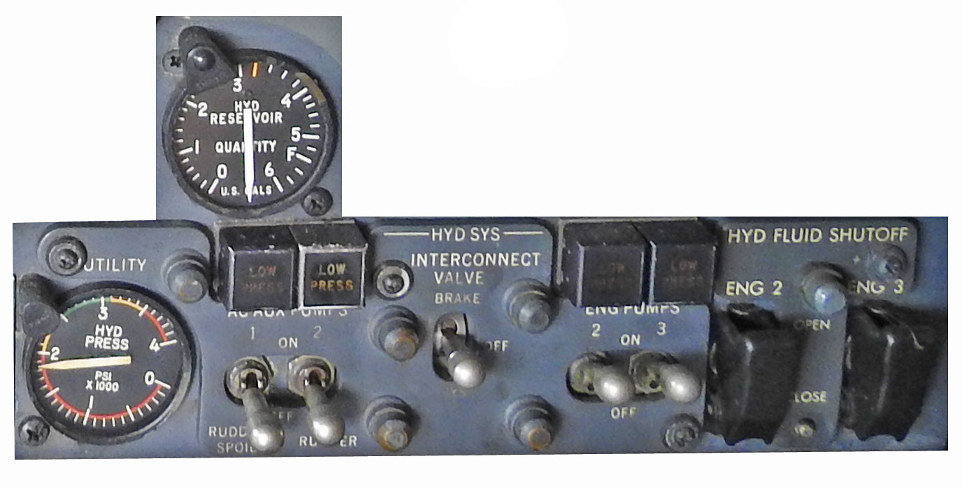
INTERCONNECT VALVE SWITCH
This switch on the F/E’s lower panel marked INTERCONNECT VALVE has BRAKE–OFF–SYSTEM positions. If placed in the BRAKE position, the switch will open the brake interconnect valve and allow the brake system to be pressurized by the auxiliary pump. This position may be used for backup operation of the brakes in the event of utility system failure. If placed in the SYSTEM position, with external power connected, the switch will open the system interconnect valve and allow the´utility system to be pressurized by the No 1 aux pump, In the OFF position both interconnect valves will be closed. If external power is disconnected, the system interconnect valve will close, regardless of the position of the interconnect valve switch.
SYSTEM INTERCONNECT VALVE
The valve is connected to the utility and auxiliary hydraulic system pressure lines. Operation of the system interconnect valve is controlled by the system interconnect valve switch on the F/E’s lower panel. Power to operate the system interconnect valve is 28V DC from J9 EXTERNAL POWER. Removal of external power prior to system interconnect valve closure will close the valve 707B/C: using 28V DC through P5, AUX HYD PUMP CONT NO 2