Boeing 707 Electrical Power
Electrical power is provided by four engine-driven AC generators. Each generator, rated at 40 KVA,
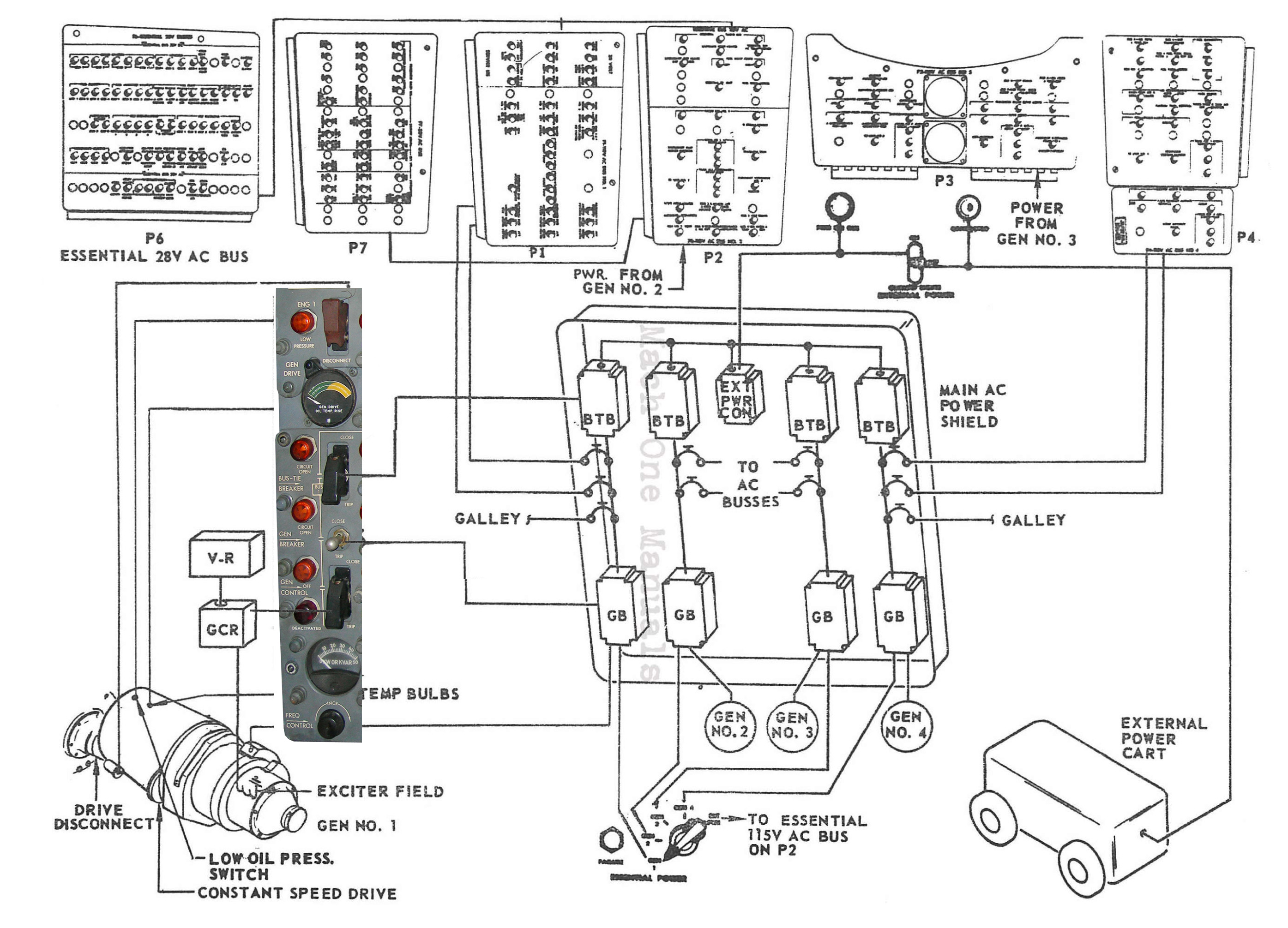
can produce 36 kilowatts continuous, 115/200 volts, 400 Hertz. Each generator is controlled by three relays operated by switches on the flight engineer’s panel. Amber lights adjacent to the switches come on when these relays are open. All three relays have automatic tripping features. Generators are driven at 6000 RPM by a constant speed drive in order to maintain 400 Hertz output.
CONSTANT SPEED DRIVE (CSD)
The controls and indicators for the CSD on the flight engineer’s electrical panel are frequency control, frequency indicator, temperature indicator, low oil pressure warning light, and disconnect switch.
The primary use of the frequency control is to adjust frequency when isolated through a range of approximately 12 cycles per second (Hertz). The frequency control should not be used when generators are in parallel. The CSD low oil pressure warning lights are normally on before starting engines. They can be used to verify that the CSD is rotating by going out when the engine N2 speed reaches approximately 15-20 %. Operating the disconnect switch energizes a solenoid on the disconnect unit which disconnects the CSD from the engine accessory drive case and trips open the appropriate main generator relay. A disconnected CSD cannot be reset in flight, but may be reset on the
ground. CSD oil temperature is expected to increase after being disconnected and will remain high until after engine shut down. The temperature is kept high by heat from the compressor section of the engine due to lack of oil circulation in the CSD after disconnection.
LOAD CONTROLLER
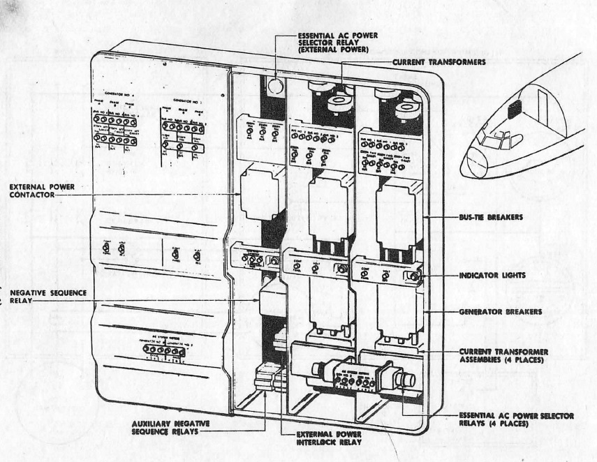
Two functions are served by the load controller. One is to control the 6000 RPM output speed of the CSD by regulating signal flow to a flyweight governor on the CSD. The other is to control and keep in balance the amount of KW load handled by each CSD and generator. Opening a bus tie or main generator relay will cut off KW balancing signals, but will continue regulating the speed of the CSD. Four load controllers are located in the electrical rack in the E & E compartment.
GENERATOR CONTROL UNIT
Each Generator Control Unit (GCD) provides generator control, as well as fault protection of the generator system. The four GCD’s are located in the electrical rack of the lower E & E compartment. With engines operating, each GCD normally has two power sources, one from the individual generator, and one from a circuit breaker on essential DC P-6. If one power source is lost, the alternate power source will be available . Both power Sources in each GCU are channeled through one DC circuit breaker On the front of the GCU and up to the cockpit switches for the appropriate GFR/MGR/BTR relays, and their indicator lights. At the ramp with all engines off, operating power for the relays and their indicator lights can be
the battery or external power.
GENERATOR CONTROL SWITCH / aka GENERATOR FIELD RELAY (GFR)
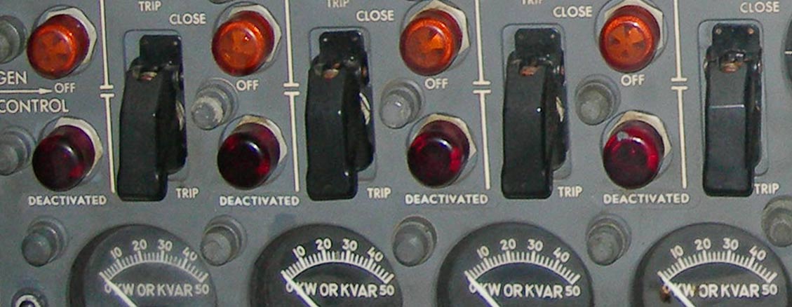
This is a small relay located in the generator control unit. When closed, it connects DC control power from the voltage regulator to the field windings of the generator. This relay has a self-latching feature and will normally remain closed, even after engine shut down. It can be tripped open by power from the GCU fault Circuit or by moving the switch to the open position. A field open light will be on when the relay has been tripped open.
Any time the generator field relay is opened, the generator breaker will also trip.
If the field relay is open when Essential bus is selected to that generator, essential AC will either be lost. Pulling an engine fire control will cause the generator field and main generator relays to trip open after 5-10 seconds time delay.
GENERATOR BREAKER
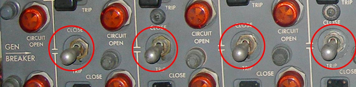
When closed, it connects the 200 volt generator output to its respective AC bus. It cannot be closed until the generator field relay has been closed and the generator is up to usable frequency and voltage. Closing the first MGR after engine start causes external power, galley and air conditioning master switches to trip off. Closing the remaining GBs is controlled by auto paralleling signals from the generator control unit. See Auto Paralleling. Normally the GB will open automatically at engine shutdown. A main generator relay can also be tripped open by either of two other circuits: turning on external power switch or operating a CSD disconnect switch.
BUS TIE BREAKER
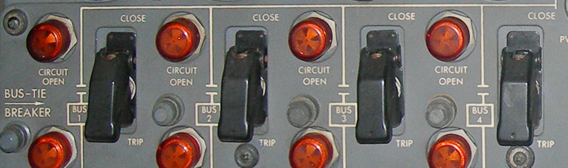
This relay is used to connect the individual AC bus to the Sync bus. When all four are closed, any AC bus may be powered from any generator. When more than one generator is operating, closing bus tie relays will provide equal distribution of power among operating generators. Bus tie relays normally stay closed at all times, both on the ground and when airborne.
If all bus tie relays are tripped in flight by a Sync bus fault, all normal and essential busses will still be powered except for those generators that may be tripped off by overload. Operating with bus ties open is undesirable because of possible overload, or losing a bus if a generator fails. If all bus tie relays trip open while at the ramp on external power, all AC busses will be unpowered.
DO NOT CLOSE THE BTB WHEN THE GB IS CLOSED UNLESS THE AC PARALLELING SELECTOR SWITCH IS POSITIONED TO THE RESPECTIVE GENERATOR AND THE SYNCHRONIZING LIGHTS ARE OUT.
SYNCHRONIZING LIGHTS
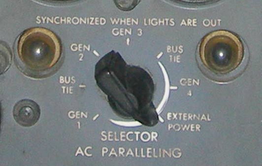
They are connected through the AC paralleling selector switch to corresponding phases of the power source selected and the synchronizing bus-tie loop . The synchronizing lights will flash on and off together or will be illuminated continuously if a slight phase, voltage or frequency difference exists. The synchronizing lights are used in manual paralleling of the generators and to check for phase rotation of the generators or external power source.
Alternate flashing of the lights indicates a phase reversal, and no attempt should be made to close the generator breaker for the particular generator or to close the external power contactor until correct phasing has been restored. The generators are normally paralleled by closing each GB with the BTB already closed. If the GB does not close, the respective BTB should be tripped, the GB closed immediately, and the BTB closed when the synchronizing lights are out . If necessary, adjust the frequency of the generator to decrease the rote of synchronizing light blinking.
ESSENTIAL POWER SELECTOR SWITCH
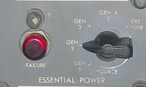
The essential AC bus is supplied directly from the generator selected, and manual tripping of the GB does not interrupt power to the bus. Automatic tripping of the GB, caused by the closing of the speed switch on the CSD, or by the tripping of the generator control relay, will interrupt power to the essential AC bus. The essential AC bus cannot be energized from external power unless the external power contactor is closed. Generator No.2 should not normally be selected for essential power, because if BTB No.2 were tripped, generator No.2 would be supplying power to both the essential radio and instrument bus and the No.2 radio and instrument bus.
CLOSING A GENERATOR BREAKER RELAY
Several actions take place when closing the first main generator breaker relay after starting engines. The CSD speed switch must operate to complete the power Circuit to the essential power selector and main generator relay switch. Moving the first GB switch to the close position energizes aux negative sequence relay #2 (in main AC power shield) Which should cause external power, galley power, and air conditioning master switches to trip off. The automatic disconnecting of external power and galley prevents overload of the first generator.
While the GB switch is being held to the close position, the external power interlock relay will operate immediately after the external power switch trips off. The external power interlock relay will operate the external power main and aux relays are open, and not welded closed. If the external power relays are open, the interlock will close sending power to the generator control unit. If the generator control unit senses that the Sync bus and the AC bus are dead, it produces a signal to dose the Generator Breaker. By this action the first generator powers all four AC busses, assuming all bus tie relays are closed.