
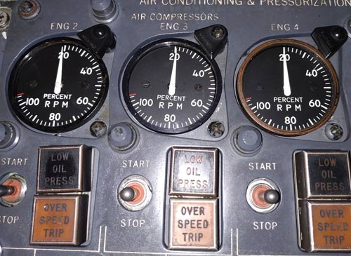
Turbo Compressor RPM indicator
Simple and quick conversion. About 4 hours total time for designing, milling and built. Uses X27 dashboard stepper motor using its internal stop for position reference.
System Description
The turbo compressor uses energy of engine bleed air (16th stage) to drive a compressor which sucks in outside air, compresses it, and sends it in for cabin pressurization and heating.
- TURBO COMPRESSOR SWITCH
When a turbo compressor switch on an operating engine is momentarily moved to START, a latching part of the switch arms the turbo compressor over speed trip light and the momentary part of the switch signals the regulator valve to open, which starts the turbo compressor. When the start switch is released, electrical power is removed from the regulator valve and air pressure which opened it now holds it open. This means that an electrical power failure will not stop an operating turbo. If electrical power is lost on an operating turbo compressor, the overspeeed protection will work but the trip light and the oil low Pressure light will not. The low oil pressure light is armed any time normal DC is available.
- BLEED AIR PRESSURE REGULATOR
Engine bleed air pressure varies with thrust lever changes, so the bleed which drives the turbo first passes through a pressure regulator to obtain a more
stable pressure source. This regulator also serves as the turbo compressor start-stop valve. When the turbo switch signals it to open, engine bleed air provides the operating
force for the valve to operate,so its engine must be running. When the turbo switch is released, electrical power is removed from the valve.
While engine bleed pressure is higher than the regulator setting, its valve modulates to supply more constant, but reduced, bleed supply to the turbine of
the turbo compressor. This allows some throttle changes within the mid to higher thrust ranges without affecting turbo compressor outputs. As engine thrust is reduced, the regulator opens wider to supply, more of the low pressure
bleed. When engine bleed pressure becomes less than the regulator setting, it opens fully but turbo compressor output ‘starts to diminish. If air pressure to the turbo becomes excessive, a shutoff valve downstream from the pressure regulator will close and stop the turbo compressor. When pressure returns to normal, the turbo compressor can be restarted in the usual way. The turbo switch stop position momentarily signals the regulator to close but engine bleed air provides the actuating force.
At high thrust settings a turbo compressor will normally be operating under the influence of the flow control, so it will turn only fast enough to put out its rated mass airflow at the existing altitude. However an altitude
can be reached at which turbo RPM will increase to 100% but does not satisfy the flow controller. When this happens a speed limiting system prevents the speed control nozzle from opening any wider bleeding
off oil pressure from the nozzle actuator. 100% is normal maximum RPM.
- OVERSPEED PROTECTION
The speed topping control serves to limit the speed of the turbo compressor to a preset maximum of 95% (46500 RPM). Should the cabin air compressor over speed a trip mechanism will operate at 112% (56,000 RPM). It can then only be reset on ground
- TURBO COMPRESSOR GROUND MODE
The flow control system normally limits turbo compressor output to its rated mass airflow. However, this is not enough air for cross-starting engines. Therefore,
when on the ground, ‘its flow control system ts bypassed causing turbo compressor RPM to follow engine RPM. At liftoff the turbo returns to fight mode, which means
its output decreases to rated flow under the influence of the flow control system. The ground mode solenoid is energized, when turbo compressor is ON, the LH safety switch is in the ground
position and one of the engine start control switches is in the GROUND START position. The GROUND START position of these switches is used only during low pressure engine starts.
- Normal indications – ground operation
1. Engine idle: 50 to 60 % rpm
2. 80 % N2: 80 % rpm
Turbo compressor RPM indication is independent of aircraft’s electrical system.
Comparison between airflow by B/A & TCs
The airflow delivered by B/A is essentially variable with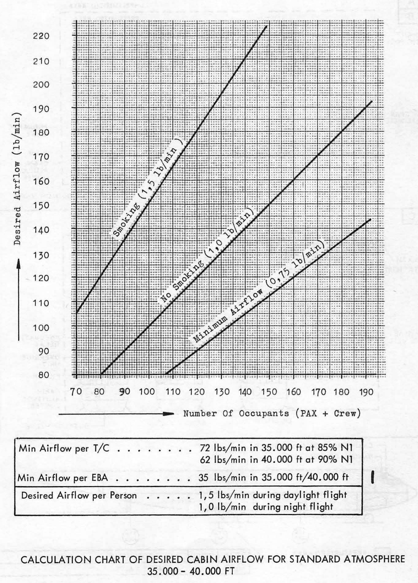
– Engine RPM
– Airplane altitude and cabin differential pressure
The influence of these factors on T/Cs airflow is negligible provided:
– Engine RPM is not near idle
– The T/C RPM is below the topping speed
At high cabin differential pressure, the best air flow is obtained by using T/C instead of B/A
After the engines are started the primary pneumatic source is from T/Cs.
Normal ops: T/C 2 and 3 ON for take off. Engine bleeds are not to be used for any take off. T/Cs reduce take of thrust.
Descent: Use all T/Cs. Only use bleeds if necessary.