
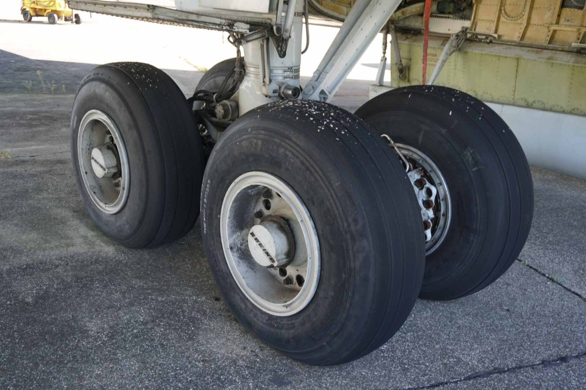
Boeing 707 — Wheel Brakes, Anti-Skid and Emergency Braking
Technical systems overview · Based on Lufthansa Technische Flugdienstvorschrift (TFV), Boeing 707 A, 707 B, 707 C, Section 10.12, Wheel Brakes; source pages include revisions dated 1966–1970. Aircraft configuration and model differences are retained where identified in the original document.
The Boeing 707 wheel braking installation combined a high-pressure hydraulic brake system, multi-disc wheel brakes, pneumatic emergency braking and an electro-hydraulic anti-skid system. Each subsystem addressed a different requirement: routine stopping and taxi control, preservation of braking capability after hydraulic failure, and the prevention of wheel lock during deceleration. Unlike a modern digitally controlled brake-by-wire aircraft, the 707 relied on mechanical pedal linkages, hydraulic metering and isolation valves, wheel-driven sensing elements and discrete electrical control circuits.
The descriptions below follow the organization and terminology of the Lufthansa training document rather than combining all Boeing 707 variants into one nominal configuration. In particular, the 707A Mark I anti-skid arrangement must be distinguished from the later Mark II installation described for the 707B and 707C.
1. System overview
The four-wheel main landing-gear bogies carry the aircraft’s wheel brakes. Hydraulic pressure normally reaches the brakes through a pedal-operated brake control system and associated protective valves. The assembly is supported by a dedicated brake hydraulic accumulator, which stores limited braking energy. An optional interconnection with the auxiliary hydraulic system is provided for a failure of the normal utility supply.
Each wheel brake is a multiple-disc unit. When the hydraulic actuating pistons apply pressure, stationary and rotating friction elements are compressed to develop the torque that slows the wheel. Heat generated during this process is absorbed by the brake assembly. Brake thermal limitations and cooldown procedures are therefore operationally important, particularly after high-energy stops.
Anti-skid is an additional control layer rather than the primary source of brake pressure. It watches wheel behavior and relieves or regulates pressure when a wheel shows excessive deceleration or an impending lock. The 707A and the 707B/707C use different anti-skid arrangements, with separate details given in the training manual.
2. Normal hydraulic braking architecture
In normal operation the brake system is pressurized from the utility hydraulic system. The brake pressure delivered to the individual wheel brakes depends on brake pedal displacement and on the operation of the brake metering valves. The brake system accepts hydraulic pressure from the utility system through the associated lockout/deboost valves. The document identifies a nominal brake system pressure of 3,025 psi and a normal system pressure of 3,500 psi.
The hydraulic system does not simply connect an unrestricted 3,500 psi supply to every brake cylinder. Metering, pressure reduction, anti-skid release and isolation functions intervene between the supply and the brake pack. The normal 3,500 psi hydraulic supply is therefore distinct from the stated 3,025 psi brake hydraulic pressure.
Normal brake pressure is applied through the pilot’s or copilot’s pedals. When utility hydraulic pressure is unavailable, the hydraulic accumulator can provide limited braking; the pneumatic emergency system serves a separate emergency function. The system also provides a means to restore normal hydraulic braking using auxiliary hydraulic pressure through the brake interconnect arrangement.
3. Brake pedals and wheel selection
The brake pedals are operated through toe pressure on either pilot’s rudder pedals. The pilot and copilot brake pedals are mechanically interconnected. The left-hand pedals command the left-hand main-gear brakes and the right-hand pedals command the right-hand main-gear brakes, permitting differential braking as well as symmetrical braking.
The operating mechanism does more than trigger a simple on/off brake command: pedal application acts upon the brake hydraulic control components and establishes the requested braking pressure. Consequently, partial pedal application can result in reduced braking action, while increasing application commands more pressure up to the system’s available capability.
The distinction between pedal demand and actual delivered wheel brake pressure matters because other devices can reduce or interrupt pressure after the pilot has requested braking, particularly the anti-skid and lockout/deboost valves.
4. Hydraulic brake accumulator
The hydraulic brake accumulator is an air-fluid cylinder, precharged to 750 psi. In the normal system the accumulator is maintained at approximately 3,500 psi. It stores hydraulic energy and permits brake application when normal utility hydraulic pressure is no longer available.
According to the Lufthansa description, the accumulator is sufficient for five full brake applications under its stated conditions. Its capacity is 200 cubic inches. These figures characterize a limited emergency reserve; they should not be interpreted as a guarantee of five identical full-energy aircraft stops under arbitrary weight, speed or runway conditions.
The accumulator should be understood as a finite pressure-and-volume source. Repeated application without replenishment progressively consumes the stored fluid volume and pressure. In a simulation, simply leaving the brake system at normal pressure after a hydraulic failure would miss one of the system’s important operating characteristics.
5. Pressure indications and limits
Two hydraulic pressure indications are provided for the brake system. The normal operating values and indicator markings in the TFV distinguish between pressure coming from the utility source, accumulator pressure, and the brake pressure delivered after regulation.
| Parameter | Value in the TFV | Meaning |
|---|---|---|
| Normal system pressure | 3,500 psi | Normal hydraulic supply/accumulator pressure |
| Normal brake hydraulic pressure | 3,025 psi | Brake pressure under the normal operating condition described |
| Accumulator precharge | 750 psi | Air precharge before hydraulic pressurization |
| Accumulator volume | 200 in³ | Specified accumulator capacity |
| System fully depressurized | 0 psi | Condition shown in the manual’s pressure indicator comparison |
The manual also notes that if brake pressure exceeds 3,500 psi, excess pressure is to be bled off by touching the brake pedals momentarily with the gear in the appropriate configuration. This is a specific historical procedure from the document, not a substitute for current aircraft-specific procedures.
6. Hydraulic interconnect valve
Following a failure of the utility hydraulic system, the brake interconnect valve allows the crew to restore normal brake operation from the auxiliary hydraulic system. The valve is controlled electrically by a switch on the flight engineer’s lower panel.
Actuation opens a motor-operated hydraulic valve, allowing one of the auxiliary system pumps to charge the brake accumulator. The document identifies a 28 V DC supply through the specified bus and pump-control circuits. The essential functional point is that the emergency reserve and the alternative hydraulic source are distinct: the interconnect can recharge or support the hydraulic brake system, while the accumulator alone cannot replace a running pump indefinitely.
7. Lockout/deboost valves
The lockout/deboost valves form a critical part of the wheel brake installation. They reduce the utility system’s pressure by the ratio described in the original manual and isolate individual hydraulic line sections from the hydraulic system for leak protection.
For the 707A, the text specifies two valves in each main-wheel well, one for each tandem pair of wheels. The 707B and 707C are described as having five valves in each main-wheel well, including separate wheel-line arrangements and associated protection. The valve count should not be normalized between variants when reconstructing the system.
The isolation function is particularly important for failure modeling: it is intended to prevent a fault in one wheel brake hydraulic line from being treated as a total failure of all hydraulic braking. The source’s individual circuit drawings should be followed for precise wheel-to-valve mapping.
8. Parking brake and warning light
The parking brake control is located on the control stand and mechanically retains a brake application. Either pilot may apply the brakes normally, then engage the parking brake handle to hold the applied condition. Releasing the parking brake does not require a separate high-pressure hydraulic command; normal pedal and mechanical release behavior is described in the handbook.
A red parking-brake warning light is installed near the parking brake handle. It illuminates whenever the parking brake is set or brake hydraulic pressure is available in the stated warning configuration. The electrical supply is identified as 28 V DC from an essential bus through the parking-brake indication circuit.
The parking brake is not independent of all hydraulic effects. Its mechanical retention of a selected brake application must be distinguished from the pressure actually available to maintain braking force. The source also identifies a parking-brake-related interaction with anti-skid valve deactivation on the 707B/707C; this is discussed below.
9. Multi-disc wheel brakes and thermal protection
The Boeing 707 uses multiple-disc wheel brakes. The illustrated assembly consists of stationary torque-reaction components, rotating friction discs, a brake piston/actuating assembly, wear indicators and associated return elements. When pressure is applied, the discs are compressed and friction resists wheel rotation. When pressure is released, the actuating mechanism permits the friction elements to separate sufficiently for wheel rotation.
Brake temperature rises with dissipated kinetic energy. The training material warns that a tire may fail violently after excessive thermal loading and that personnel must not assume the danger has disappeared immediately after the aircraft has stopped. The relevant warning emphasizes that inflated aircraft tires must be approached with particular caution after abnormal braking or suspected wheel overheating.
The brake drawings differentiate details of the 707A and 707B/707C brake packs, including the depiction of the deboost arrangement and brake wear indicators. The brake-pack schematics therefore matter for a mechanically faithful reconstruction, even if the pilot-level braking concept is similar.
10. Anti-skid operating principle
The anti-skid system is installed to improve braking effectiveness and prevent excessive wheel skidding during heavy braking. It does not create braking demand; instead it acts on the hydraulic pressure delivered to the brakes when the wheel-speed sensing and control circuits indicate excessive wheel deceleration.
The original system consists of three functional categories: a wheel-speed sensor or anti-skid detector, a control circuit, and an anti-skid hydraulic valve. As wheel speed changes, the detector produces information used to decide whether brake pressure needs to be relieved. When the wheel recovers, the system allows braking pressure to build again.
The handbook states that the system adjusts available braking toward the maximum compatible with the runway surface and wheel behavior. Its operational result is a sequence of controlled pressure reductions and recoveries, not a fixed reduction in pedal authority. Details of sensor technology and the number of control channels depend on the 707 variant.
11. Anti-skid wheel-speed detectors
The anti-skid detectors are axle-mounted and wheel-driven. Their purpose is to produce an electrical signal related to wheel rotation. The 707A Mark I uses a flywheel arrangement with a rattle-clutch mechanism. The 707B/707C Mark II arrangement is identified in the manual as a variable-reluctance transducer.
In the Mark I arrangement, the mechanical relationship between the wheel and flywheel changes during rapid wheel deceleration, producing the detector’s output. The original documentation notes behavior of the clutch at high speed and a transition to different operation at lower speed. In the Mark II design, a rotor and magnetic stator produce an electrical frequency proportional to wheel speed. A control circuit can detect excessive deceleration from the rate of change of the signal.
This distinction matters for a historically faithful simulator: a wheel speed measurement alone is not a complete anti-skid model. The system needs to recognize rapidly changing wheel speed and then regulate pressure with the control and hydraulic response characteristics of the fitted system.
12. Mark I anti-skid — Boeing 707A
The TFV assigns the Mark I anti-skid installation to the 707A. The detector is identified as the axle-driven flywheel/rattle-clutch type. The 707A installation uses wheel detectors in each main-wheel well, with control shielding and valve behavior arranged around tandem-pair braking.
The source describes anti-skid control logic in which a rapid wheel deceleration triggers hydraulic brake pressure reduction. Following the pressure-release event, brake pressure increases again. The pilot need not deliberately pump the brakes in order to make the anti-skid system operate; the automatic circuit provides pressure modulation when enabled and when the necessary wheel behavior is detected.
Mark I operation is described with model-specific test equipment and brake-release indications. It should not be represented in a simulator merely by renaming a modern anti-skid switch, because its sensing and distribution differ from Mark II.
13. Mark II anti-skid — Boeing 707B and 707C
The 707B and 707C use the Mark II (new) anti-skid system described in the source. These aircraft have a wheel-driven variable-reluctance detector and control circuitry that interprets the wheel-speed signal. The system includes brake-pressure control valves arranged as a paired hydraulic assembly in the illustrated installation.
The control shield receives and processes sensor information. The associated anti-skid valves reduce brake pressure when necessary and allow restoration of pressure as the wheel recovers. The TFV describes an anti-skid arrangement that automatically adjusts braking effort according to runway condition, with more modern electronic sensing than the Mark I mechanical flywheel detector.
The Mark II system also has aircraft-specific interactions with parking-brake and test circuits. The schematic and system text establish that these are not merely annunciations: the corresponding electrical switches determine whether anti-skid valve control is active and what feedback reaches the crew.
14. Anti-skid controls, test and indications
Anti-skid switch
A guarded ANTI-SKID switch on the overhead panel selects the system ON or OFF. The documentation identifies 28 V DC electrical supply and dedicated bus/circuit protection for the anti-skid equipment. The guard and switch position are part of the installation’s intended operational logic.
Brake-released indicators
Brake-released indicators provide a direct indication of anti-skid-induced brake release. The indicators are normally visible in the pilot’s instrument panel. During an anti-skid action the relevant indicator changes state to indicate that an associated brake or tandem pair has been released by the system.
The timing and arrangement are variant dependent. The TFV states that the 707A brakes become available approximately 0.7 seconds after touchdown. On the 707B/707C, anti-skid release is inhibited below a wheel speed corresponding to approximately 11.7 mph, and the document specifies the relevant control-switch behavior. These values belong to their particular configurations and should not be applied indiscriminately to all versions.
Mark II test provisions
The Mark II installation includes an overhead anti-skid system test switch with the positions described in the source, including INBD–OFF–OUTBD. The test permits the crew to verify parts of the brake-release indication and anti-skid circuitry without relying solely on a real wheel-skid event. The tests are associated with inner and outer wheel circuits, providing a useful division for fault isolation.
Parking brake interaction
On the 707B/707C, the manual specifies that setting the parking brake deactivates the anti-skid valves. This is a meaningful system relationship, not just an indicator-lamp effect. It prevents the automatic anti-skid release function from overriding the aircraft’s parking-brake configuration.
15. Pneumatic emergency braking
A separate pneumatic brake system is provided for emergency use only. It is not intended to supplement normal hydraulic braking during routine operation. The Lufthansa instructions caution against attempting to use the pneumatic emergency system concurrently with normal hydraulic brake pressure.
The compressed-air system uses a bottle charged to approximately 1,200 psi. The document states that the pneumatic supply provides at least five full brake applications under the specified conditions. The emergency brake control has ON–HOLD–OFF positions. Its function is to apply pneumatic pressure to the emergency brake actuating arrangement when hydraulic brake capability has been lost.
The emergency brake system has a pressure gauge in the control-stand area, with the fully charged indication at approximately 1,200 psi. Unlike normal differential pedal braking, the emergency system is a separate manual brake supply and must not be assumed to reproduce the normal hydraulic pedal modulation or anti-skid function.
The system can provide stopping capability after major hydraulic loss, but the amount of available air is finite. Each full application consumes some of that reserve. A simulator should therefore model the emergency bottle pressure independently from the normal utility hydraulic system and the hydraulic accumulator.
16. Operating recommendations and brake energy
The TFV devotes a section to reducing brake heat buildup and tire/brake damage. The emphasis is not simply on achieving a short stopping distance but on managing energy, cooldown time and the risks associated with repeated heavy brake applications.
Normal rollout and taxi
After landing, the document recommends using aerodynamic and other decelerating effects as appropriate to limit the amount of energy absorbed by the brakes. In normal operations the crew should avoid prolonged brake dragging or unnecessary brake application while taxiing. The hydraulic brakes are powerful enough to accumulate significant heat at high aircraft weights even when the aircraft is not moving at landing speed.
Brake cooldown considerations
The recommendations include specific combinations of rollout distance, stop severity and gear-down cooling time. One example states that an unrestricted number of rollout stops from 6,000 ft each may be followed by 15 minutes of airborne gear-down cooling. Another example addresses rolling stops from 5,000 ft with an associated 20-minute cooling period. These are not universal performance rules; they belong to the historical cooling and energy guidance and must be read with its underlying assumptions.
The manual also distinguishes single and repeated maximum-effort stops from less demanding braking sequences. It warns that substantial heat remains in the brake equipment after stopping and that excessive heat can be transferred to the wheels and tires. The guidance assumes the use of appropriate braking technique and aircraft-specific brake energy charts.
Maximum braking and training operations
Maximum braking should not be treated as the routine braking method simply because it is available. The Lufthansa document recommends using minimum brake energy sufficient for the operation and gives separate advice for training flights where several high-energy braking events may occur close together.
During training, repeated full-stop landings or rejected-takeoff exercises may impose cumulative energy loads on the brake system. The crew must account for cooldown periods between maneuvers and for the possibility that wheel or tire temperatures lag behind the apparent cessation of brake heating.
17. Failure behavior and system interactions
The brake system contains several independent or partly independent fault paths. A loss of utility hydraulic pressure does not necessarily imply an immediate complete loss of braking, because stored pressure in the accumulator can be used and the auxiliary hydraulic system may be connected through the interconnect valve. These two options are distinct and should be represented separately.
Failure of a brake line may activate isolation behavior within the lockout/deboost valve arrangement, affecting the relevant hydraulic section. An anti-skid failure is not identical to loss of hydraulic brake pressure: the brakes may still be hydraulically commanded, but automatic release/protection may no longer be available. Likewise, parking brake engagement produces an intended anti-skid interaction on the Mark II aircraft.
Emergency pneumatic braking provides a final, separately stored pressure source after hydraulic failure, but does not eliminate the limitations imposed by stored pressure volume, tire/runway conditions or brake heat. These distinctions are central to understanding the aircraft’s braking system as a collection of interconnected mechanisms rather than a single brake switch.
18. Notes for X-Plane and hardware-simulator implementation
The following subsection is an implementation interpretation, not a claim that the TFV specifies a software architecture. A faithful reconstruction of the wheel brake system in X-Plane could separate pilot brake demand from system pressure, actual brake-cylinder pressure, wheel rotation, anti-skid valve state, and stored emergency energy. This would allow the simulator to reproduce the logic described in the historical manual rather than relying entirely on a generic modern wheel-braking model.
Recommended simulated inputs
Relevant inputs would include left and right brake pedal displacement, parking brake handle, hydraulic supply pressures, accumulator charge, interconnect switch, anti-skid power and test controls, wheel speed on each braked wheel, touchdown and weight-on-wheel state, pneumatic emergency brake handle, and emergency bottle pressure. Aircraft ground speed, individual wheel slip and brake temperature would be useful for physical realism, though their exact modeling equations are not supplied in this source.
Recommended simulated states
Internally, model separate left- and right-side brake pressure demand, utility and auxiliary pressure availability, accumulator pressure and remaining usable fluid volume, emergency bottle pressure, lockout/deboost valve isolation state, wheel-specific anti-skid release state, and brake/wheel thermal energy. Where possible, distinguish the Mark I and Mark II sensor/controller behavior.
Recommended outputs
Outputs could include per-wheel or per-pair braking torque, cockpit brake-pressure indications, anti-skid brake-release indicators, parking brake warning lamp, emergency brake pressure indication, and test-circuit indication. These outputs could drive original or recreated 707 hardware independently of the X-Plane flight dynamics interface.
Parameters that must not be invented
The TFV provides several important pressure values, component descriptions and some control timings, but it does not provide every required coefficient for a high-fidelity numerical model. Exact brake torque versus pressure, brake-pad friction versus temperature, per-wheel thermal capacity, anti-skid closed-loop gains and detailed pneumatic application flow rates must be obtained from additional source material or clearly identified as engineering approximations during testing.
19. Source and interpretation notes
This article summarizes the attached Lufthansa Technische Flugdienstvorschrift, Section 10.12 — Wheel Brakes, covering general operation, hydraulic brake system and components, anti-skid system and components, pneumatic emergency braking and brake usage recommendations. The source also includes component, hydraulic and wiring illustrations not reproduced here, at the user’s request.
The 707A and 707B/707C differences are preserved as documented. Values in this article are historical source values, not current certification limits or operating instructions. Numerical behavior and proposed software decomposition in the simulator section are clearly distinguished from original manual statements. The scanned source contains variant-specific material and partial schematic pages; detailed electrical/wheel-line mapping should be verified against the original drawings before implementing hardware logic.