
Boeing 707 — Radio, Navigation and Weather Radar Systems
Based on Lufthansa Technical School training manuals for the Boeing 707/720 and Bendix RDR-1E.
1. Introduction
The Boeing 707 entered service at a time when long-range flight depended on a combination of radio communication, ground-based navigation aids, independent radio-navigation receivers and specialized radar equipment. The Lufthansa Technical School publication Radioanlagen 707/720 covers the installations of the Boeing 707-430, 707-330B and 720-030B. It notes differences between aircraft versions where relevant. Its printed sheets include revisions from different dates, so the document should not be treated as a single frozen aircraft configuration. This chapter combines that overview with the separate Lufthansa Technical School publication RDR-1E Wetter-Radargerät, Chapter 34-32, February 1968. The radio systems are introduced first, followed by a detailed examination of the Bendix weather radar and its distinctive electromechanical and storage-tube technology.
The document is organized around equipment functions rather than a modern integrated flight-management concept. Each installation has its own controls, signal paths, antennas and indicating instruments. Some systems provide information directly to the pilots; others support communication between stations or supply measurements to additional instruments. Understanding the aircraft therefore requires following the entire chain from a cockpit selector to a remote equipment rack, an antenna and, where applicable, an indicator.
The descriptions below retain the terminology of the Lufthansa training material. They should be read as an introduction to the historical installations, not as evidence that every Boeing 707 carried identical equipment throughout its service life. Airline modifications, individual aircraft and later upgrades could alter the configuration.
2. Electrical Supply and Equipment Cooling
The original radio manual treats electrical supply and equipment cooling before individual radio installations. This reflects an essential feature of early jet avionics: transmitters, receivers, amplifiers and power supplies could require substantial electrical power and forced cooling. A cockpit control alone does not define whether equipment is available; its supply, circuit protection, installation-specific switching and cooling must also be considered. The manual provides separate sections for power distribution and the equipment cooling system. When reconstructing these systems, electrical dependencies should be based on the aircraft-specific diagrams rather than assumed from the presence of an illuminated control.
The electrical and cooling chapters are placed before the communication systems for a practical reason: a radio unit can be electrically selected yet remain unavailable if a required supply is absent. Different subsystems may depend on separate power sources, and an equipment rack may require ventilation even when its controls are located in the cockpit.
In a historically faithful reconstruction, the relevant questions are not only which switch turns a unit on, but also whether the corresponding supply is present, whether the unit is in a warm-up or operating condition and which indicators are powered. The Lufthansa wiring and supply diagrams, rather than generalized assumptions about later jetliners, should determine those dependencies.
3. Interphone, Service Communication and Passenger Address
The interphone system connects cockpit crew members, cabin attendants and ground servicing positions. The Lufthansa manual identifies audio selector panels, an interphone amplifier, forward and aft flight-attendant stations, exterior service-interphone connections, microphones, headsets and a monitoring loudspeaker. Audio selection is central to the installation: a crew member must be able to select an appropriate source and distinguish internal communication from external radio traffic. The cabin loudspeaker system is documented separately. In a faithful simulator, the various communication paths should remain distinct rather than being mixed into a single always-on audio channel.
The audio selector panel is the interface between the person using the system and the available audio sources. It determines what the crew member hears and, together with microphone selection, where speech is transmitted. The interphone amplifier and associated wiring make communication possible between positions that may be physically far apart within the aircraft.
External service stations serve a different operational purpose from cockpit-to-cockpit conversation. During ground operations, technicians may need to communicate with the flight deck while engines, electrical power or other aircraft systems are being handled. The manual therefore treats the service-interphone outlets and the flight-attendant stations as parts of a larger aircraft communication installation.
Passenger announcements are related to, but functionally distinct from, crew interphone. A reconstruction should preserve that distinction: transmitting over the public-address system is not the same action as speaking to another headset position, and listening to an ATC receiver does not automatically mean that its audio is heard at every station.
4. HF Communication
High-frequency communication supported long-range operations beyond the normal reach of VHF ground stations. The Lufthansa manual describes the HF equipment, antennas, antenna tuning units, interlocks and operating arrangements. It contains separate subsections for the Boeing 707-430, Boeing 707-330 and Boeing 720-030B, making it important to consult the appropriate aircraft version. HF operation depends on more than a selected frequency: antenna tuning and the correct transmitter/receiver configuration are part of the system. The manual is a technical description of the aircraft installation, not a guarantee of reception quality under any particular ionospheric conditions.
HF communication addresses a fundamental problem of long-range flight: beyond the horizon, an aircraft cannot always maintain contact with a nearby VHF ground transmitter. HF offers a different propagation mechanism, allowing signals to reach distant stations under suitable ionospheric conditions. That advantage comes with changing reception quality, atmospheric noise and the need for correct antenna matching.
The Lufthansa material devotes particular attention to antenna tuning and operating interlocks. These are not incidental details. A transmitter and its antenna form an electrical system, and a tuning unit is needed to present a suitable load over the selected frequency range. Interlocks can prevent inappropriate operating combinations and protect equipment.
The manual distinguishes the HF arrangements of the 707-430, 707-330 and 720-030B. Those differences should be retained when documenting an individual Lufthansa 707-330B cockpit; the mere existence of a control on another model is not proof of identical wiring or operating logic.
5. VHF Communication
The VHF communication installation provides the routine radio link between the flight crew and air traffic services within ground-station coverage. The Lufthansa documentation covers cockpit controls, transmitters, receivers, antennas and operation. It is distinct from the VHF navigation installation discussed later in this chapter. For a cockpit reconstruction, the relevant tasks are to reproduce control selection, audio routing and the appropriate operating indications while preserving the aircraft-specific equipment arrangement.
The VHF installation is described in terms of its cockpit control panels, transmitter, receiver, antennas and operating sequence. These separate elements explain why a frequency selection on the panel is only one part of a successful radio transmission. The selected radio must also receive electrical power, be connected to its antenna and be selected through the appropriate audio and microphone controls.
VHF’s predominantly line-of-sight propagation made it well suited to communication with nearby air traffic control facilities. Its usable range varies with aircraft altitude, terrain and station location. HF and VHF were therefore complementary rather than interchangeable systems on a long-range Boeing 707.
6. SELCAL and Static Dischargers
The selective calling system, SELCAL, allows a ground station to alert a particular aircraft without requiring the crew to continuously monitor every received voice transmission. The manual describes the control equipment and SELCAL receiver. Static dischargers are treated in a separate section. They are intended to reduce interference associated with electrical charge on the aircraft, especially precipitation static. These are different systems, but both are relevant to the practical usability of airborne radio communication.
SELCAL reduced the burden of continuous listening, especially during long HF sectors. A ground station could transmit the aircraft’s assigned calling signal, and the onboard equipment would recognize the corresponding combination and alert the crew. The system did not replace the voice radio: it provided an attention-getting function so that normal radio communication could then take place.
Static dischargers address a separate source of communication difficulty. As the aircraft moves through precipitation and charged particles, electrical charge can accumulate and discharge, producing radio-frequency interference. The manual includes static dischargers as part of the overall radio installation because good reception depends on the aircraft’s external electrical environment as well as the receiver itself.
8. DFA-70 Automatic Direction Finding
The Lufthansa document identifies the DFA-70 ADF installation and explains its receiver, tuning arrangement, loop antenna, sense antenna, sense-antenna coupler and Radio Magnetic Indicator (RMI) presentation. The directional loop and sense antenna functions must be considered together when explaining how an unambiguous bearing is obtained. The manual provides the technical foundation for representing the original receiver and indicator behavior, rather than merely calculating an ideal bearing from the aircraft position.
The DFA-70 chapter separates the receiver, tuning mechanism, loop antenna, sense antenna and sense-antenna coupler. The loop antenna responds directionally to the incoming radio field, but a loop-only measurement can contain a 180-degree ambiguity. The sense-antenna arrangement supplies the additional information needed to resolve the direction.
The resulting direction information is displayed on the Radio Magnetic Indicator. Consequently, the visible RMI pointer is only the final stage of a longer signal chain. Its behavior depends on the receiver being correctly tuned, the incoming signal being usable and the directional equipment functioning as intended.
For a period-correct simulation, the tuning behavior and antenna-related indications deserve attention alongside the pointer animation. The Lufthansa manual provides the original system organization, but any detailed failure behavior should be taken from the relevant diagrams and maintenance descriptions rather than inferred from modern ADF equipment.
9. LORAN Navigation
The manual includes an extensive treatment of LORAN and the EO-LORAN receiver. LORAN navigation is based on measuring the time differences between signals received from geographically separated transmitting stations. The resulting measurements establish lines of position. The operator’s task involves recognizing and comparing pulse patterns, which is fundamentally different from selecting a waypoint on a modern flight-management system. For a historical simulation, the visible pulse display, signal timing and station geometry are integral to the navigation method. The radio manual describes the principle and receiver function; exact reproduction of a particular route or historical station network requires period-specific station information.
LORAN is particularly different from VOR or ADF because the operator is not simply reading a bearing to a station. The equipment receives timed pulse transmissions from a network of stations. By comparing their arrival times, the navigator obtains a time difference corresponding to a hyperbolic line of position. Two suitable measurements can be combined to establish a position.
The EO-LORAN receiver chapter covers the reception and measurement process. The timing relationship between the pulses is the central quantity; the displayed traces are a means of identifying and comparing those signals. This is why the characteristic oscilloscope-style presentation is essential to understanding the original equipment.
A simulation that reproduces only a numerical position would miss much of the historical operating task. A closer reconstruction would model station selection, pulse timing, receiver presentation and the operator’s interpretation of the time differences. Exact station coverage and operating procedures, however, require period-specific charts and instructions beyond the general equipment description.
10. AVQ-9 Radio Altimeter
The AVQ-9 is described in the Lufthansa radio manual under radio altitude measurement, including its operating principle, block diagram, controls and screen presentations. A radio altimeter determines distance to the reflecting surface below the aircraft, unlike a barometric altimeter, which indicates altitude derived from atmospheric pressure. The AVQ-9 presentation and controls belong to the historical equipment installation and should not be confused with the later digital radio-altimeter indicators. The original manual should be consulted for its exact scales and operating sequence.
The AVQ-9 chapter explains both the measurement principle and the distinctive presentation used by the equipment. Unlike a pressure-derived altitude, radio altitude is referenced to the reflecting surface beneath the aircraft. It therefore changes with the underlying terrain even if the aircraft maintains a constant barometric altitude.
The manual discusses a normal measurement range and a temporarily selectable extended range for coarse measurements. This difference matters when interpreting the instrument: a scale change alters the relationship between the displayed trace and the measured distance. The original display should not be confused with the later small digital radio-altitude readouts familiar from more modern flight decks.
Because the measured quantity depends on radio reflection, the presentation is also tied to the characteristics of the surface and the receiving system. A historically accurate description must preserve that distinction rather than treating radio altitude as an infallible geometric value.
11. ATC Transponder
The ATC transponder is covered in a separate section dealing with its general principle, control unit, transponder equipment and operation. Unlike primary surveillance radar, which detects reflected energy, secondary surveillance relies on an active response from the aircraft to a ground interrogation. In a reconstruction, the transponder should therefore be treated as a separate radio system with its own controls and electrical supply, rather than as a function of the weather radar.
Secondary surveillance differs from primary radar in a basic respect. A primary radar station detects energy reflected from the aircraft, while a secondary surveillance system interrogates an onboard transponder and receives an actively transmitted reply. This allows information associated with the aircraft to be displayed and interpreted by ground equipment.
The Lufthansa manual divides its explanation into general principles, the cockpit control unit, the transponder itself and the operating method. The distinction is useful because the control panel selects the operating condition while the remote equipment handles interrogation and reply. An instrument replica should represent the documented controls and responses rather than automatically assuming features introduced in later transponder generations.
12. Doppler Navigation and DME
The manual identifies the DN-101 Doppler radar and NC-103 flight-path computer, as well as the DME-860 E-2 distance-measuring installation. Doppler navigation uses frequency shifts in reflected signals to obtain information about motion over the ground. The documentation refers to a separate training publication for the full Doppler description and notes an additional junction unit, called a “marriage box”, in the Boeing 707-330B installation. DME uses timed radio interrogation and reply signals to determine slant distance to a compatible ground station. These systems serve different navigation purposes and should not be conflated with the RDR-1E weather radar.
Doppler navigation uses the frequency shift of radio energy reflected from the surface to derive information about aircraft movement relative to the ground. The associated flight-path computer can use this measurement as part of the navigation solution. The Lufthansa material identifies the DN-101 radar and NC-103 computer and points to additional documentation for their detailed operating principles.
DME uses a different method. The aircraft sends interrogations to a compatible ground station, which replies after a defined delay. The airborne equipment measures the timing relationship and presents slant distance. Because it is slant range, the indicated distance is not always identical to horizontal distance across the ground, particularly near the station at significant altitude.
These systems illustrate the variety of independent navigation techniques carried aboard early jet transports. Their indications were useful for different tasks and were not equivalent substitutes for one another.
13. Bendix RDR-1E: System Overview
The Lufthansa Technical School’s February 1968 RDR-1E Wetter-Radargerät publication describes the principles and major components of the Bendix airborne weather radar. Its first part introduces pulse radar, propagation, microwave generation, waveguides, antennas and storage-tube display principles. The second part explains the RDR-1E installation, transceiver, antenna servo and stabilization, indicator, controls, power supply, tests and maintenance. The RDR-1E was designed to show weather echoes ahead of the aircraft and to provide a ground-mapping presentation. Its display was produced by electronic circuits and a specialized cathode-ray tube, not by digital image processing. The principal units described include the antenna, PPI-1E indicator, control panel, transmitter/receiver and waveguide installation.
The RDR-1E comprises an antenna installation, a transmitter-receiver assembly, a control panel and a PPI-1E indicator. The units are connected by waveguides, electrical wiring and synchronization signals. Radar echoes begin as microwave reflections at the antenna but reach the pilot as visible patterns on the indicator after amplification, detection and display processing.
The February 1968 Lufthansa Technical School publication is arranged in two parts. The first explains radar physics, microwave generation, waveguides, antenna characteristics and storage-tube display technology. The second follows the actual RDR-1E assemblies, operating modes, tests, stabilization system and power supply. This chapter follows that technical logic while combining it with the broader radio-installation overview.
14. Pulse-Echo Principle and Radar Range
The transmitter emits brief pulses of microwave energy. Objects and precipitation scatter some of that energy back toward the aircraft. The receiver measures the returning echo, while the antenna position provides directional information. Because the pulse travels to the target and back, target distance equals the speed of light multiplied by the echo delay and divided by two. An echo arriving approximately 123.5 microseconds after transmission corresponds to a distance of 10 nautical miles. The manual explains that radar returns are influenced by the amount of energy reflected toward the receiver, antenna characteristics, propagation losses and receiver sensitivity. Rain, hail and other precipitation can produce returns, but an echo is not a direct measurement of turbulence. Strong precipitation can also attenuate signals and conceal more distant targets. Radar interpretation must therefore take the limitations of microwave propagation into account.
At the documented pulse repetition frequency of 400 pulses per second, consecutive transmissions are separated by 2,500 microseconds. The transmitter is active for only a small fraction of that interval. During the remaining time the receiver listens for echoes and the display associates their arrival time with distance.
The manual discusses how the duration of each pulse affects the ability to distinguish two nearby targets along the same bearing. A longer pulse occupies a greater length in space, so reflections from closely spaced targets may overlap. The nominal 2.5-microsecond pulse corresponds to a spatial pulse length of about 750 metres, or a two-way range extent of roughly 375 metres. This is a physical limit relevant to the appearance of small or closely spaced returns.
The manual also describes the radar horizon, beam width, receiver sensitivity and attenuation. These factors mean that a missing echo is not proof of clear conditions. A distant target may be beyond useful range, hidden behind stronger precipitation, outside the selected vertical beam or too weak to produce a visible return.
15. RDR-1E Technical Characteristics
The manual identifies a nominal operating frequency of 9,375 MHz, corresponding to a wavelength of approximately 3.2 cm in the X-band. The pulse repetition frequency is 400 pulses per second, and the pulse duration is 2.5 microseconds. The discussion of the transmitter gives a peak pulse power of approximately 50 kW. The antenna reflector is approximately 30 inches in diameter and rotates at roughly 15 revolutions per minute, giving a complete revolution in about four seconds. Antenna tilt can be commanded from 15 degrees up to 15 degrees down. The PPI-1E indicator offers selectable 20, 50 and 150 nautical mile scales. These are historical system parameters, not specifications for any modern replacement display.
| Parameter | Value |
|---|---|
| Nominal frequency | 9,375 MHz |
| Pulse repetition frequency | 400 Hz |
| Pulse duration | 2.5 µs |
| Approximate peak power | 50 kW |
| Antenna reflector | 30 inches |
| Antenna rotation | 15 RPM |
| Tilt | ±15° |
| Range scales | 20 / 50 / 150 NM |
| Indicator | PPI-1E storage tube |
The listed characteristics are the nominal training-manual values. They describe the basic radar architecture but do not by themselves define every visible behavior of the display. For example, the number of range rings is determined by the indicator timing circuits, while the antenna’s four-second rotation period determines how frequently a given azimuth is revisited.
The 20-, 50- and 150-NM selections are display scales, not guarantees that every target can be detected at those distances. Actual detection depends on target reflectivity, attenuation, antenna pointing and receiver performance. The manual’s separate discussion of range and sensitivity is important for interpreting these figures correctly.
16. Magnetron Transmitter, Duplexer and Receiver
The RDR-1E transmitter uses a magnetron to generate high-power microwave pulses. A modulator supplies the required pulse energy. A duplexer allows the antenna to be shared by the transmitter and receiver: during transmission, it protects the sensitive receiver from the transmitter output; between pulses, it directs returning echoes into the receiving circuits. The receiver converts the incoming microwave signal through intermediate-frequency stages. The Lufthansa block diagrams identify 60 MHz and 13.5 MHz intermediate-frequency sections, local oscillators, mixing stages, video detection and amplification. Automatic frequency control helps maintain the correct relationship between the magnetron and receiver oscillators. Sensitivity-time control reduces the influence of exceptionally strong nearby returns. The pilot’s gain selection provides a further means of adjusting the display response. These functions interact; receiver gain should not be interpreted simply as a cosmetic brightness control.
The transmitter’s magnetron generates microwave energy at approximately 9,375 MHz. The modulator supplies short high-voltage pulses, and the duplexer routes the resulting energy toward the antenna while protecting the receiver. After each transmission, the receiver must recover quickly enough to detect returning echoes, including relatively nearby ones.
The receiving chain employs two frequency-conversion stages. The first intermediate frequency is 60 MHz; a second conversion produces a 13.5-MHz intermediate frequency before detection and video processing. The AFC system maintains the required relationship between the magnetron frequency and the local oscillators. This is an important feature of a magnetron-based radar because the transmitter frequency is not perfectly fixed.
Sensitivity-time control deliberately reduces the response to early, usually nearby, echoes. Without this compensation, strong short-range reflections could dominate the picture while more distant targets remained comparatively faint. The manual also describes gain control and contour processing, both of which influence what the pilot sees rather than changing the physical location of precipitation.
17. Antenna, Beam Switching and Stabilization
The radar antenna is installed behind the nose radome. Its approximately 30-inch parabolic reflector concentrates transmitted energy and receives returning echoes. The antenna rotates in azimuth while a separate mechanism adjusts elevation. In weather observation, the antenna employs a beam characteristic suitable for detecting precipitation ahead of the aircraft. Ground mapping uses a different polarization and a cosecant-squared beam characteristic to represent ground reflections over a useful distance range. The manual illustrates these differences with beam-switching and directional diagrams. The antenna is stabilized against aircraft pitch and roll through gyro inputs and servo circuits. The Lufthansa radio manual specifies Vertical Gyro No. 1 for the Boeing 707-330B and Vertical Gyro No. 2 for the 707-430 and 720-030B. The RDR-1E training document includes detailed stabilization block diagrams and describes how commanded tilt, attitude inputs and feedback signals influence the antenna drive.
The antenna installation contains the reflector, feed, azimuth drive, elevation drive and position-feedback components. The approximately 30-inch reflector concentrates the transmitted energy and receives echoes from a relatively narrow angular region. As the antenna rotates, the indicator’s azimuth reference must track its actual position.
The beam-switching arrangement changes the antenna characteristics between weather observation and ground mapping. In the normal weather configuration the system uses a narrow pencil-like beam. In mapping mode the manual describes a vertically shaped cosecant-squared pattern, intended to produce a more useful distribution of ground returns at different distances. This is a real antenna characteristic, not merely a different screen color or software filter.
Stabilization uses aircraft pitch and roll information from the appropriate vertical gyro together with antenna position feedback and servo circuitry. The objective is to maintain the selected beam orientation despite aircraft attitude changes. For the Lufthansa 707-330B the radio manual identifies Vertical Gyro No. 1 as the source; the 707-430 and 720-030B use No. 2. The commanded tilt remains a separate input from the corrections made by stabilization.
18. PPI-1E Storage-Tube Indicator
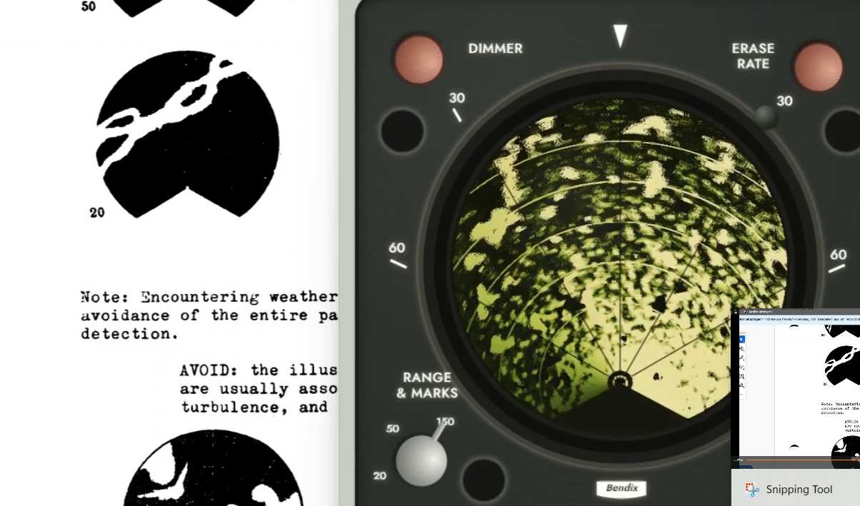
The PPI-1E is one of the system’s defining features. Its plan-position presentation places the aircraft at the origin and represents echo range radially, synchronized with antenna azimuth. The indicator uses a viewing-storage cathode-ray tube rather than a conventional raster display. Received radar video controls a writing beam, while the stored charge pattern influences the visible image. The manual describes the writing and viewing electron systems and the storage mesh. Radar returns can therefore remain visible after the writing beam has passed. This persistence is not equivalent to simply drawing permanent pixels on a modern screen. The indicator has an ERASE RATE control for adjusting image retention, a fast-erase function for clearing the stored picture, brightness and trace adjustments, and an adjustable optical filter. The original display’s appearance results from the interaction of antenna movement, range sweep, writing intensity, storage behavior and erasure.
The PPI-1E is not a modern raster screen. The indicator generates a radial writing sweep synchronized with the transmitted pulse and the antenna’s azimuth. Received video signals change the writing-beam intensity at the corresponding range. The resulting stored charge pattern governs the visible presentation.
The storage tube contains a writing system and a separate viewing mechanism. This arrangement allows an image to remain visible between antenna passes instead of disappearing immediately after the writing beam has moved on. The manual includes a cutaway drawing and a graph showing the relation between storage-layer conditions and screen brightness.
ERASE RATE controls how quickly stored information is removed. This affects whether old echoes remain visible after the antenna has passed, and how easily the pilot can recognize changing patterns. The fast-erase button clears the image more quickly when the old picture is no longer useful. TRACE ADJUST and brightness-related controls influence the appearance of the sweep and the resulting image. The optical filter in front of the screen further changes the perceived contrast and color.
These effects are essential to the historical character of the radar. A continuously repainted image with no persistence or erasure behavior would reproduce the geometry of a PPI but not the operation of the original PPI-1E.
19. Radar Controls and Operating Modes
The separate radar control panel provides the operating-mode selector, GAIN and ANT TILT controls. The documented selections include OFF, STBY, weather normal (WX NOR), weather contour (WX CTR), MAP and TEST. STBY prepares the equipment without normal transmission. WX NOR is the standard weather presentation. WX CTR changes the treatment of particularly strong returns to provide contour information. MAP selects the ground-mapping arrangement. TEST produces a defined artificial pattern for checking system behavior. The GAIN control includes an AUTO setting. ANT TILT permits approximately 15 degrees of upward or downward adjustment. The manual describes an equipment warm-up requirement and a test procedure; these should be followed from the original publication rather than generalized from modern radar operating habits.
The main selector combines standby, weather and mapping functions with a test facility. In normal weather operation the display represents received precipitation echoes. Contour operation changes the processing of strong returns so that high-reflectivity regions can be distinguished by a characteristic dark contour within the echo pattern.
MAP selects the ground-mapping antenna configuration. It is intended for reflecting terrain features and coastlines rather than the normal weather presentation. The change involves antenna polarization and beam characteristics as well as the interpretation of the returns.
The GAIN control permits receiver sensitivity adjustment, with an AUTO position provided on the control panel. ANT TILT commands the antenna upward or downward within its marked range. The separate indicator controls manage brightness, trace and stored-image erasure. For accurate operation, these control groups should not be conflated: receiver gain, antenna pointing and storage-tube persistence affect different parts of the radar signal chain.
The manual describes a warm-up procedure following standby and includes a dedicated self-test presentation. The specific timing and test sequence should be followed from the original instructions rather than replaced with generic modern radar logic.
20. Range Selection, Rings and Sweep Timing
The PPI-1E indicator has three range scales. On the 20 NM scale, four rings are separated by 5 NM. On the 50 NM scale, five rings are separated by 10 NM. On the 150 NM scale, six rings are separated by 25 NM. The indicator generates a radial sweep whose timing is changed with the selected range. Electronic range marks are added to the display at the appropriate intervals. The training manual provides the relevant sweep-time and ring-spacing calculations. Correct synchronization is essential: an echo’s distance on the screen must remain consistent with the selected range, and the ring marks must follow the same timing. A historically faithful reconstruction should not simply rescale an already-rendered picture without considering sweep and storage behavior.
| Range | Rings | Spacing |
|---|---|---|
| 20 NM | 4 | 5 NM |
| 50 NM | 5 | 10 NM |
| 150 NM | 6 | 25 NM |
The range selector changes the time base of the radial writing sweep. For a 20-NM selection the beam must cover the displayed radial distance in a much shorter interval than for the 150-NM selection. The indicator therefore changes the sweep rate as the range is changed.
Range rings are generated by timed electronic pulses. Their spacing corresponds to 5 NM on the 20-NM scale, 10 NM on the 50-NM scale and 25 NM on the 150-NM scale. The manual gives the associated ring timing and frequency calculations. These marks are generated by the indicator electronics; they are not physical echoes received from the environment.
A simulation should calculate echo placement from the actual round-trip propagation time, then apply the selected display scale. It should generate the range rings independently and keep them synchronized with the sweep. This reproduces the functional separation shown in the Lufthansa indicator block diagram.
21. Self-Test, Maintenance and Safety
The RDR-1E includes a self-test arrangement that creates a recognizable test pattern on the PPI-1E indicator. The training document includes a photograph of this pattern and block diagrams of the test-signal paths. It also describes transceiver monitoring, antenna and stabilization faults, ring-time measurement and maintenance precautions. The equipment contains high-voltage circuitry and a powerful microwave transmitter. Original service precautions therefore remain important when handling real surviving equipment. The historical training publication is not a substitute for current approved maintenance documentation or safety procedures.
The self-test arrangement injects artificial signals into the radar processing chain and produces a recognizable pattern on the PPI-1E. The training manual includes both a photograph of the expected test display and block diagrams of the test-signal path. This makes the test mode a useful reference for verifying indicator geometry and the behavior of the video circuits.
The maintenance section describes characteristic symptoms such as unstable antenna motion, incorrect display indications and faults affecting synchronization or signal processing. These descriptions should be interpreted as historical maintenance information, not as instructions for unqualified repair of a live transmitter.
The system contains high voltages and generates high-power microwave pulses. The original documentation includes safety precautions concerning antenna operation, personnel near the radome and equipment handling. Restoring original transmitting equipment requires appropriate specialist facilities and safety procedures.
22. Historical Reconstruction in a Boeing 707 Simulator
Reconstructing the RDR-1E requires the original control logic and display behavior to be treated as one system. Important elements include mechanically timed azimuth scanning, selected antenna elevation, gyro-based stabilization, weather and ground-mapping beam behavior, receiver gain, contour processing, range-specific sweep timing, electronic range rings and the storage-tube erase characteristics. A modern weather data source may provide precipitation information, but the image shown to the pilot should be generated through a model of the original instrument’s behavior. The original Lufthansa manuals document many of these relationships. Where the documents do not establish a precise numerical response, that uncertainty should remain explicit rather than being replaced with invented settings. The purpose is to recreate the original crew interface and its limitations, not to turn the Bendix indicator into a modern weather display.
The most direct reconstruction separates the system into three layers. First, a radar-target model determines which weather or ground reflectors lie inside the antenna beam at each instant. Second, the RDR-1E receiver model applies gain, sensitivity-time control, attenuation and contour logic. Third, the PPI-1E display model writes returns at the correct azimuth and range and removes them according to the selected erase behavior.
A mechanically plausible antenna model should rotate at the documented speed and use the selected tilt with attitude-stabilization corrections. Ground mapping should change the beam model rather than simply applying a cosmetic effect. Likewise, range rings should arise from the timing model, and TEST should generate the documented internal pattern rather than arbitrary decorative graphics.
This architecture is a proposed simulation method, not a claim that Lufthansa used digital processing. Its purpose is to reproduce the behavior of the historical analogue equipment while retaining a clear distinction between documented properties and software implementation choices.
23. Index of the Original Lufthansa Manuals
The following index uses the printed sheet numbers of the Radioanlagen 707/720 manual. They are not the PDF viewer’s page numbers. The separate radar training publication has its own pagination and is identified below.
| Original section | Subject | Printed sheet |
|---|---|---|
| 1 | Foreword | 1 |
| 2 | General information | 2 |
| 3 | Electrical supply | 11 |
| 4 | Equipment cooling | 16 |
| 5 | Interphone and service communication | 23 |
| 6 | Cabin loudspeaker system | See original contents |
| 7 | HF communication | See original contents |
| 8 | VHF communication | 52 |
| 9 | SELCAL | 57 |
| 10 | Static dischargers | 61 |
| 11 | VHF navigation | 63 |
| 12 | DFA-70 ADF | 83 |
| 13 | LORAN | 92 |
| 14 | AVQ-9 radio altimeter | 103 |
| 15 | Weather radar | 108 |
| 16 | ATC transponder | 111 |
| 17 | DN-101 Doppler / NC-103 | 115 |
| 18 | DME-860 E-2 | 116 |
RDR-1E separate publication: Part I covers general radar principles; Part II covers the RDR-1E equipment, block diagrams, stabilization, indicator, controls, antenna, power supply and testing. See the original table of contents on PDF pages 3–4.
The index below uses the original Lufthansa section and sheet references. These printed numbers are not identical to the page numbers of the scanned PDFs. Readers comparing the website with the source material should therefore use the original chapter headings and printed sheet numbers when possible.
The separate RDR-1E training booklet contains a general radar-theory part followed by the system-specific description, block diagrams, indicator details, antenna stabilization and maintenance information. Its PDF illustrations are especially useful for understanding how the equipment was connected and how the test image was expected to appear.
24. Sources and Scope
Primary sources: Lufthansa Technische Schule, Radioanlagen 707/720, Chapters 23 and 34 (1960s training publication with dated revisions); Lufthansa Technische Schule, RDR-1E Wetter-Radargerät, Chapter 34-32, issue 2.68. This chapter is an English-language technical summary for historical study and simulation. It does not reproduce every installation diagram or maintenance procedure and must not be used as an operational or approved maintenance manual. Boeing 707 variants and equipment revisions are distinguished only where supported by the cited manuals.
Descriptions of the communication and navigation installations follow the Lufthansa Technical School Radioanlagen 707/720 manual. The radar details follow the February 1968 RDR-1E training publication. General explanatory language is used to connect the documented components, but unlisted aircraft-specific operating limits and later equipment features are intentionally not assumed.