
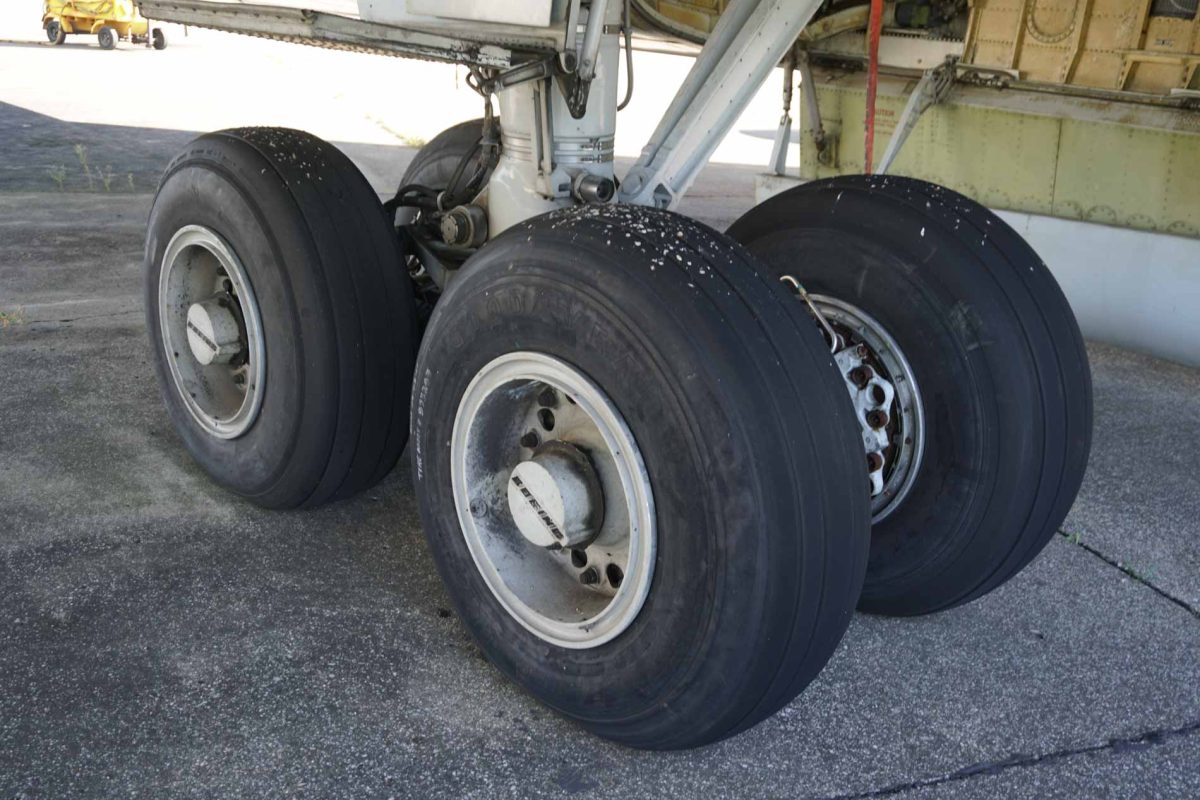
Boeing 707 Landing Gear System
Technical description of the main and nose landing gear, hydraulic control, mechanical locking, ground safety devices, indications, emergency extension, and optional weight-and-balance system
Based on the Lufthansa Technische Flugdienstvorschrift (TFV), Boeing 707 A/B/C, Chapter 10.10, including historical illustrations and aircraft-variant notes. This is an educational technical summary of the supplied period documentation, not an approved maintenance or flight operating procedure.
1. System overview
The Boeing 707 uses a hydraulically operated, retractable tricycle landing gear. It consists of two main landing gear assemblies, each carrying a four-wheel truck, and a steerable nose landing gear fitted with two wheels. All three assemblies are controlled by a single landing-gear control handle in the pilots’ center panel, but their mechanisms, locks, and door arrangements are not identical. A number of mechanical and electrical protections prevent inadvertent operation and provide the crew with information about whether the gear is fully extended, locked, moving, or not in its commanded condition.
The Lufthansa technical manual treats the landing gear as a linked system rather than simply three hydraulic actuators. The complete operating sequence depends on selector and sequence valves, gear and door actuators, lock actuators, position switches, and mechanical linkages. A successful indication requires the relevant lock and position conditions; merely moving a wheel assembly to an approximately extended location does not by itself establish the correct locked state.
The main wheels are arranged to allow the truck assembly to assume the correct attitude for stowage. The nose gear is mechanically centered for retraction. Ground locks, warning lights, a landing-gear warning horn, and an emergency extension system provide additional protection. In the original aircraft, the main gear wheels also have provisions to prevent residual wheel rotation after takeoff. Thus, both hydraulic movement and the less visible mechanical events matter when reconstructing the operation of the system.
The TFV states that gear extension or retraction takes approximately 10 seconds under normal conditions. This is an approximate system description, not a guaranteed timing figure for every operating condition or aircraft variant.
2. Landing gear construction and geometry
The two main legs are supported by a substantial shock-strut and bracing arrangement. The shock strut absorbs landing loads, while the truck beam supports the four wheels and permits relative movement about its pivot. The arrangement provides the aircraft with load-carrying capacity, maintains the required ground attitude, and allows the entire gear to be folded into the fuselage/wing-root wheel-well region.
The main gear assembly includes the trunnion, shock strut, drag strut, side strut, folding and locking links, actuator beam, truck assembly, torsion links, and wheel and brake installations. The manual’s location diagram distinguishes the truck-leveling and truck-centering mechanisms, and notes variant differences in how the truck is aligned during the retraction sequence. These details are important because the main landing gear is not a rigid leg that rotates into a bay without changing its own geometry.
The nose gear contains a telescopic shock strut, steering collar, torque-link arrangement, tow fittings, wheel spacer, drag brace, lock mechanism, door-operating linkages, and hydraulic actuators. The nose assembly retracts rearward into its compartment. Its steering function must be correctly aligned during the retraction cycle: the mechanism includes a centering action rather than relying on the wheels to happen to be straight when the landing-gear lever is moved.
During flight, the landing gear and associated doors are subject to aerodynamic loads. On the ground, loads instead pass through the tires, shock struts, braces, and their attachments. This distinction is reflected in the design of the downlocks, mechanical ground locks, and the logic that inhibits unsafe retraction.
3. Flight deck controls and hydraulic selection
The landing-gear control handle is located on the pilots’ center panel. The documented handle has three detented positions: UP, OFF, and DN. These correspond to retraction, removal of the commanded hydraulic operating action, and extension. The handle is connected to the landing-gear selector valve and is also subject to a protective locking arrangement.
When the control handle is moved, hydraulic fluid is routed through the gear selector valve to the relevant control and sequence components. The system then uses hydraulic and mechanical sequencing to coordinate door operation and gear movement. The main gear selector valve and the separate nose gear sequence components do not make the three legs mechanically identical; rather, they are coordinated through their own subsystems.
The OFF position deserves attention. On a vintage hydraulic system it is not simply an inactive label on the control pedestal. Returning the handle to OFF changes the hydraulic control condition after a completed cycle. A software reproduction must therefore differentiate between a steady-position indication and a continuously energized command to move the gear.
The control handle is normally locked to prevent unintended selection of UP when the aircraft is supported on its landing gear. An override trigger is provided, but the historical manual explicitly warns against using it casually. The override is not a normal means of retracting the gear and cannot replace the appropriate ground safeguards.
4. Main landing gear assemblies
4.1 Shock strut, side strut, and drag strut
Each main landing gear is hinged at its principal aircraft attachment and is stabilized by bracing members when extended. The shock strut accommodates vertical landing loads, while the side and drag struts maintain the geometry required for ground operations. Folding and locking members allow these braces to change shape during retraction but resist unwanted collapse in the fully deployed position.
The main gear lock assembly includes a lock hook, lock bungee, actuator linkage, position and control valve elements, and mechanical connections to the gear/door logic. The design distinguishes between the gear reaching its extended geometry and the lock mechanism fully securing that geometry. The lock function is therefore central to both safety and correct cockpit indication.
4.2 Four-wheel truck and truck leveling
The four main wheels are mounted on a truck assembly. Truck leveling controls the beam attitude as the landing gear moves between the extended and stowed positions. The drawings show a specific truck-leveling cylinder for the earlier arrangement and a truck-centering-cylinder arrangement on later variants. These are not interchangeable terms: they identify differences in the mechanism used to position the truck for retraction.
The leveling/centering system prevents the wheel truck from adopting an unsuitable orientation as it approaches the wheel well. It is linked to the gear’s mechanical geometry and hydraulic operation. Its role should be modeled separately from the main retraction actuator, since the truck angle is a dependent mechanical state rather than merely an arbitrary animation.
4.3 Wheel rotation and brake interface
The manual notes a provision for stopping main-wheel rotation after takeoff. This is significant because the wheel brake and landing gear systems have related, but distinct, responsibilities: the gear system retracts and locks the assemblies, while residual wheel rotation must be brought under control before the wheel equipment is enclosed. The exact brake system details are treated elsewhere in the TFV and are not reconstructed here from the landing gear chapter alone.
5. Main gear locks, side struts, and ground locks
The main landing gear relies on mechanical locks in addition to hydraulic pressure. With the gear extended, the side strut is held in its overcenter position and is positively secured. The lock actuator and associated linkage permit it to be released when retraction has been selected and the hydraulic sequence has reached the appropriate stage. Conversely, extension requires the side strut to straighten and the lock to engage before the gear can be regarded as properly down and locked.
The main gear ground locks are separate maintenance and ground-safety devices. The manual describes one ground-lock installation per main gear, with a warning streamer. Their role is to prevent gear retraction while the aircraft is parked or being serviced, even if some other control or hydraulic condition changes. Ground locks must not be confused with the automatically operating airborne downlock mechanisms.
Mechanical lock geometry also determines switch states used by the cockpit indications. For example, a gear can be visibly low without its downlock being fully engaged. That distinction is intentional: the warnings concern secure configuration, not simply approximate leg position.
6. Main landing gear retraction and extension sequence
6.1 Normal retraction
Selection of UP initiates the hydraulic gear-up sequence, subject to the landing-gear handle interlock. The system coordinates release of the main gear downlock, wheel-well door movement, and the gear actuator. The main landing gear cannot simply be driven upward against closed doors or an engaged mechanical lock. The door and lock control valves and hydraulic sequence provide the necessary ordering.
As the gear leaves the extended position, the braces fold, the main gear rotates toward the wheel well, and the truck-leveling or truck-centering arrangement positions the wheel truck for stowage. The gear assembly is then secured in its up position by its associated locking mechanism. The doors complete their own commanded movement according to the control sequence.
The historic sequence illustrations show separate pressure and return lines, the gear door control valve, sequence components, and main gear actuator. They should be interpreted as an interacting hydraulic circuit; an apparently simple UP command initiates a chain of valve and mechanical events.
6.2 Normal extension
Selection of DN reverses the appropriate hydraulic control conditions. The gear-well doors are released/opened in the required sequence, the main gear is moved toward the extended position, the side struts straighten, and the locking mechanism establishes the down-and-locked condition. The door system subsequently completes its own travel.
A green cockpit indication is associated with a properly locked gear. The manual’s distinction between position and lock is therefore important when interpreting transient indications as the main gear moves. The green light must not be treated as a simple function of actuator extension percentage. It represents the result of the relevant switch/lock logic.
6.3 Why the sequence matters
Three elements have to agree: hydraulic command, mechanical configuration, and electrical indication. A loss of hydraulic pressure, an improperly sequenced door, or a lock that fails to engage can create different outcomes even if a simplified animation would show the gear in roughly the same place. The TFV’s dedicated drawings for main gear UP and DOWN were intended to explain precisely such interactions.
7. Wheel-well doors and door sequencing
The main landing-gear compartments are covered by movable doors. The drawings identify door operating mechanisms, an actuator beam, door links and connecting rods, return and pressure piping, door control valves, and lock/safety-valve arrangements. The operation of these components is tied to gear movement but is not identical to the movement of the landing-gear leg.
The TFV illustrates an arrangement in which selected wheel-well doors may be operated from the ground for inspection or servicing. The dedicated ground-door release mechanisms are provided for controlled use with the aircraft stationary. The manual emphasizes that the appropriate gear safety conditions and pressure precautions must be observed before attempting such operation.
Door position must also be distinguished from gear position. A gear can be locked down while a particular door remains open for inspection; similarly, an in-flight door fault does not necessarily mean the gear itself has reached an unsafe configuration. This is why the aircraft includes independent gear-door warning indications.
7.1 Door warning lights
A red DOOR warning light on the pilots’ center panel illuminates whenever a landing-gear door is not properly closed and locked. This indication is independent of the red landing-gear warning logic. On the flight engineer’s auxiliary panel, a door-warnings test switch provides a means to verify the relevant indication circuit.
7.2 Door ground-release provisions
The manual also describes main landing-gear door ground-release handles, including precautions against operating the doors while the system remains pressurized. The handles are maintenance/ground servicing controls rather than normal flight deck controls. Their exact operation is tied to the specific door and lock linkage shown in the diagrams.
8. Nose landing gear and steering interfaces
The steerable nose gear is a distinct assembly with its own shock strut, wheels, drag brace, centering provisions, lock and retention actuators, and door-control mechanism. It is designed to retract rearward. The nose gear must be correctly aligned before entering its wheel well; centering of the steering system is an integral part of the extension/retraction arrangement.
Its assembly drawings identify the steering collar, steering cylinders, steering disconnect pin, towing collar and lug, torque-link components, nose gear actuator, lock actuator, lock assembly, and operating/retention mechanisms. Although the steering and gear functions share physical components, the full nose-wheel steering hydraulic control system belongs to a separate TFV chapter and should not be assumed to be completely defined by this landing gear extract.
8.1 Nose gear lock
The nose gear lock mechanism uses a lock crank/rod and retention arrangement to secure the gear. The nose gear’s drag brace and lock are coordinated with its hydraulic actuator. The illustrations show both lock and unlock conditions, confirming that nose gear movement and lock release must be handled as separate events.
8.2 Nose gear ground lock
A dedicated nose gear ground-lock handle and ground-lock pin are shown. The lock prevents retraction while installed; the manual instructs that the pin be removed before taxiing and the ground-lock arrangement be restored to its normal configuration. These are important physical safety devices, not merely cockpit indications.
9. Nose gear hydraulic sequence and locking
9.1 Gear-up operation
The nose gear’s hydraulic diagram includes the selector valve, a nose gear sequence valve, gear door control valve, gear and door actuators, and a valve restrictor. During a normal gear-up sequence, the system releases the extended locking condition, controls the nose-gear doors, and draws the nose gear into the well. The mechanism centers the wheels for stowage. Once retracted, the gear is held by the designed uplock/retention arrangement.
9.2 Gear-down operation
When DN is selected, hydraulic and mechanical sequencing releases the appropriate stowage retention, opens the nose-wheel well as required, extends the gear, and engages the extended locking arrangement. The drawings demonstrate that pressure and return paths change during the sequence rather than simply reversing one motor. A complete down indication depends on the corresponding lock and position switch states.
9.3 Nose door release and disconnect mechanism
Separate illustrations show a nose gear door-release mechanism and nose gear disconnect link. This arrangement permits the gear/door mechanical relationship to be changed for specific ground or emergency requirements. The source includes physical linkages and release components, but those illustrations should not be converted into a general maintenance procedure without the applicable aircraft-specific instructions.
10. Gear position indication and warning systems
10.1 Three green landing-gear lights
Three green landing gear position lights on the pilots’ center panel are identified as LEFT GEAR, NOSE GEAR, and RIGHT GEAR. They illuminate only when the associated gear is down and locked. A DIM control changes the brilliance of the lamps; it does not change the underlying lock status.
10.2 Red GEAR warning light
The center panel also carries a red GEAR warning light. It operates when a landing gear is not down and locked under the conditions specified by the landing-gear lever and warning logic. The warning system is not intended to duplicate three green lamps with a single inverted switch; it combines commanded gear position and actual secured state.
10.3 Red DOOR warning light
The separate red DOOR indication alerts the crew to a landing gear door not closed and locked. It can therefore be active independently of the individual landing gear green lights.
10.4 Landing-gear warning horn
The landing-gear warning horn provides an audible alert when gear configuration is incompatible with the applicable flight/control conditions. The related warning horn cutout lever provides a means to silence the horn in specified situations. The manual distinguishes conditions under which the horn can be silenced from those under which the warning persists. The horn circuit is linked to the warning system described in the separate TFV Warning Systems chapter, and that chapter should be consulted for complete throttle/flap-triggered criteria.
10.5 In-flight inspection provisions
The manual describes access for inspection of main landing gear wheel-well and nose landing gear lock mechanisms. On some versions, mechanical main-gear position-and-lock indicators supplement the electrical cockpit indication. An inspection provision is useful when an indication is questionable, but it must not be confused with a substitute for an approved operational procedure.
10.6 Mechanically observed main-gear position (707C)
The 707C description includes main-gear mechanical indicators visible from inspection points. Indicators on the associated gear lock/shaft arrangements can show the gear-down-and-locked state by a combination of colored marks/patches and flag positions. The visual arrangement is described separately for main gear lock and position; its purpose is to corroborate that the mechanism is in the required condition.
11. Safety interlocks and ground operation
A gear handle interlock prevents ordinary retraction selection when the aircraft is on its wheels and the appropriate ground-sensing and lock conditions are present. The TFV describes a handle override trigger that can bypass the normal restriction, but it attaches explicit warnings to its use. The interlock is part of an overall safety philosophy that also includes gear ground locks and independent indications.
The document describes the use of landing-gear oleo-operated safety switches as aircraft ground/air status inputs. These switches have wider functions than the landing gear itself: they provide ground/flight state information to systems throughout the aircraft. Therefore a robust simulation must avoid treating a single generic “gear down” Boolean as equivalent to the oleo-compressed condition.
On the ground, the landing-gear doors may be moved for maintenance purposes only under the specified safety conditions. The manual cautions against retracting a gear when any landing gear fails to extend normally, because such movement can result in damage to gear and/or doors. The correct response in the historical text is to preserve the existing safe configuration and perform appropriate investigation, not to repeatedly cycle the gear.
11.1 Distinct states that matter
- Aircraft weight on wheels versus airborne status.
- Gear handle commanded UP, OFF, or DN.
- Gear physically up, moving, or down.
- Gear mechanically locked or unlocked.
- Individual doors closed/locked or not.
- Ground-lock devices installed or removed.
- Hydraulic system available or failed.
- Electrical indication power available or lost.
These variables are separate in the physical aircraft. Combining them into one single gear-position variable conceals many of the exact behaviors that the TFV explains.
12. Manual and emergency extension
The Boeing 707 incorporates a manually operated emergency gear-extension system for use when normal hydraulic extension is unavailable. The manual describes access from the control cabin, operation of cranks in the floor/sidewall area, and separate provisions associated with the main and nose gears. Emergency extension is a mechanical release-and-deployment arrangement, not just a second hydraulic pump for the normal sequence.
12.1 Main landing gear emergency extension
The main gear arrangements include emergency controls that release the applicable gear and door locks. The mechanism permits the gear to move toward its extended position under the available forces after its retention is released. The drawings identify manual cranks, door-release cables, linkage assemblies, and downlock-related components. These parts must operate in the correct order to prevent the door or the gear from remaining mechanically restrained.
12.2 Nose landing gear emergency extension
The nose gear emergency system includes a manual operating and locking arrangement. The TFV devotes several illustrations to the emergency nose gear mechanism and an associated lock system, with identifiable intermediate states such as door released, gear unlocked, and gear free to extend. This is more complicated than a single emergency “gear down” command and should be understood as a sequence of latch/shaft positions.
12.3 Emergency extension lock positions
A particularly informative drawing shows a sequence of nose gear emergency extension lock positions and the interaction between inner and outer shafts, lock cam, and detent. The logic ensures a defined progression through release and movement. The last configuration is a neutral/restored condition. For a detailed engineering reconstruction, those discrete states can be represented directly rather than hidden within an instantaneous emergency extension animation.
12.4 Emergency-to-normal restoration
The original document describes means of securing the emergency-extension equipment after operation and returning the relevant mechanisms to their normal operating condition. Such restoration is not identical to merely moving the cockpit gear lever. It requires the emergency release/locking mechanisms to be in the corresponding position. The supplied illustrations explain the mechanism but are not a complete aircraft release-to-service checklist.
13. 707A, 707B and 707C differences
The TFV covers several 707 configurations and explicitly cautions that variant-specific details must be read with the notes in the illustrations. Not every 707 installation uses identical truck-leveling/centering hardware or identical inspection and indicating equipment.
13.1 Earlier and later truck positioning mechanisms
The main landing gear drawings distinguish a truck leveling cylinder for an earlier main-gear arrangement and a truck centering cylinder for later variants. The engineering purpose is related, but the physical assemblies differ. A period-specific reproduction should follow the correct configuration rather than treating all main landing gear trucks as mechanically interchangeable.
13.2 Gear indication
707C equipment may include the mechanical main-gear position-and-lock inspection indicators shown in the TFV. The location and flag interpretation should be kept consistent with that version. Electrical gear position switches and the pilots’ green indications exist as part of the broader landing gear system but do not supersede these particular mechanical inspection provisions.
13.3 Weight-and-balance installation
The manual marks the pressure-transducer weight-and-balance system as installed on the aircraft types specified in its variant note, rather than as a universal characteristic of every 707. Aircraft-series applicability must therefore be checked before presenting this system as standard equipment.
13.4 Model-specific source limitation
Some drawings identify 707, 707B, 707C, and/or 720B configurations; other pages use a later TFV chapter heading that applies to A/B/C. The summary preserves these distinctions where explicit but does not infer that a drawing for one configuration establishes the exact build standard of all Lufthansa 707-330B aircraft.
14. Weight-and-balance (STAN) system
The TFV includes a separate section on a weight-and-balance (STAN) system, an unusually interesting feature from the perspective of historical aircraft instrumentation. Instead of deriving weight solely from a manually prepared loading document, this system uses pressure measurements from the landing-gear shock struts to estimate the aircraft’s gross weight and center-of-gravity position while on the ground.
14.1 Pressure sensing and electrical calculation
A pressure transducer is fitted at each relevant landing-gear shock strut. These transducers generate electrical signals as a function of the respective shock-strut nitrogen pressure. The signals are sent to an electronic calculation box mounted on the flight engineer’s lower panel. That unit calculates indicated takeoff gross weight and center-of-gravity position, expressed as percentage of mean aerodynamic chord (% MAC).
The manual identifies 115 V AC as the system power supply. Because the measurement is based on pressure and landing-gear loading, it inherently relates to ground support conditions and does not amount to an independent airborne mass measurement.
14.2 Flight engineer’s display and test switch
The lower flight engineer’s panel contains a Take-Off Gross Weight (TOGW) and % MAC indicator and a momentary TEST switch. A source-specific test description states that selecting TEST causes the TOGW display to indicate 995 ± 15 (100 kg units) and the % MAC display to indicate 18.2 ± 0.5%. These figures describe the instrument test response, not the actual loaded weight or center of gravity of an aircraft.
14.3 Interpretation and limitations
Shock-strut based measurement depends on the calibration and physical state of the landing gear, and the TFV excerpt provides the overall architecture rather than a full mathematical solution for the weight calculation. A faithful simulation could reproduce the indication and test behavior, but should label any invented sensor characteristics, damping values, or weight/CG algorithms as derived assumptions rather than original Lufthansa data.
15. Electrical power, switches, and system interfaces
The main gear position indicating and warning circuits use electrical switches at the landing gear mechanisms. The drawings include landing-gear and door switch positions, circuit protection, ground/air safety logic, warning-horn connections, and indication circuits. The page titled Landing Gear Position Indicating System Circuit is particularly useful because it brings the cockpit lamps and dispersed gear-mounted switches into one electrical representation.
The manual shows 28 V DC supply for landing-gear position and warning indications. The separate weight-and-balance system is shown as a 115 V AC installation. These should not be collapsed into one undifferentiated electrical bus. A simulator replicating circuit-breaker behavior or bus failures needs to preserve the relevant sources, protective devices, and switch states.
The warning-horn circuit is related to the position indicating and airplane configuration warning systems. Door-warning electrical logic is likewise separate from the green gear-lock indication. On the real aircraft a loss of lamp power, a failed switch, a gear that is unlocked, and an open door produce different physical conditions even if some combinations look superficially similar to the crew.
15.1 Gear-position switches
The drawings distinguish between gear-position and gear-lock actuation. This distinction allows the aircraft to determine whether a strut is merely in a particular angular position or has actually achieved the necessary locked state. A software representation should not drive these electrical contacts from the same threshold without evaluating their intended mechanical actuation points.
15.2 Cockpit indicator dimming and tests
The pilots’ center-panel lamps include a dimming feature; certain associated circuits can be tested from the flight engineer’s auxiliary panel. These controls are display-related, not gear-actuating, and belong in the electrical/indicator layer of any reconstruction.
16. Operational behavior and failure considerations
The TFV chapter provides the normal mechanical and electrical sequence rather than a complete abnormal-procedures handbook. Even so, it explains several important categories of behavior that should be understood independently.
16.1 Hydraulic failure
Failure of the normal hydraulic gear operating path can prevent normal retraction or extension, while emergency extension remains mechanically available through its separate release system. The actual extent of gear travel after a failure depends on which component has failed and on the gear/door/lock configuration at that instant. It is not technically sufficient to equate any hydraulic pressure loss with immediate complete gear extension.
16.2 Failure to lock
If the landing gear extends but the downlock mechanism does not complete its motion, the corresponding safe indication may remain absent. The warning system is specifically designed to distinguish this state from a secured landing gear. A partial lock is therefore fundamentally different from a failed indicator lamp, even if both can result in missing green indication.
16.3 Door faults
Failure of the gear doors to reach or remain in their required closed position can trigger the DOOR warning while the gear is otherwise in a known position. The fault may involve the door actuator, lock, linkage, or a switch. The original drawings make clear that door motion is mechanically and hydraulically coupled to, but not identical with, gear travel.
16.4 Unintended retraction safeguards
Ground locks and the cockpit handle interlock are complementary safeguards. The manual repeatedly warns that improper override or ground-door operation can endanger personnel and damage the aircraft. The system should consequently be understood as having multiple independent barriers against retraction on the ground.
16.5 Mechanical inspection
Physical inspection provisions and the mechanical indicators on relevant aircraft versions can help establish the state of lock mechanisms when cockpit indications are suspect. These historical provisions illustrate why mechanically confirmed and electrically indicated states need to be modeled separately.
17. Implications for a faithful flight simulator
For a historical Boeing 707 simulator, the landing gear is an excellent example of a system that benefits from state-based mechanical logic rather than a basic up/down animation. X-Plane can provide airframe physics, weight-on-wheels state, gear movement representation, and the surrounding flight environment. An independent gear-system model can then represent the gear selector, hydraulic availability, door sequence, downlocks, uplocks, interlocks, and associated warning circuits.
17.1 Recommended independent mechanical states
- Three individual gear travel states, with motion and timing rather than instantaneous changes.
- Independent main and nose gear downlock and uplock conditions.
- Door-open, door-closed, and door-locked states for the applicable compartments.
- Main-gear truck angle and the correct leveling or centering behavior for the simulated variant.
- Nose wheel centering and steering disconnect behavior.
- Hydraulic selector, sequence-valve, and pressure availability states.
- Weight-on-wheels and landing-gear handle lock/override states.
- Separate emergency release crank/cable and lock states.
- Ground safety pins, installed ground locks, and inspection-door release states where the hardware is reproduced.
17.2 Recommended indications
Drive LEFT, NOSE, and RIGHT green lights from lock-confirming logic; drive red GEAR from the manual’s warning logic; drive red DOOR from the corresponding door-lock state; and drive the warning horn from the configuration-warning criteria. Keep indicator power and dimming separate from mechanical positions. This architecture permits realistic failures such as a fully down gear with a failed indicator circuit, or a gear that physically reaches the bottom of travel but fails to secure its lock.
17.3 Normal and emergency interaction
Normal hydraulic extension should follow the door, unlock, actuator, and lock sequence described by the TFV. Emergency extension should release the required locks and permit deployment through its own mechanism. For the nose gear in particular, the manual’s discrete emergency lock-shaft positions suggest a more faithful state machine than a single emergency toggle.
17.4 What cannot be determined from this chapter alone
The supplied landing gear section is sufficiently detailed to establish functional architecture and most of the intended operating order. It does not provide every component’s pressure/flow characteristic, all actuator stroke times, exact switch trip tolerances, the full brake-control logic, or a complete mathematical calibration for STAN. Those values require further, type- and configuration-specific documentation or clearly identified simulator approximations.
18. Source and scope
Primary source: Lufthansa Technische Flugdienstvorschrift (TFV) Boeing 707 A, 707 B, 707 C, Chapter 10.10 “Landing Gear”, sections 10.10.0 through 10.10.4, including the period system component descriptions and technical illustrations supplied in the 47-page scan. The collection includes material and correction dates from the mid-1960s onward and multiple aircraft-variant illustration headers.
This article is a newly written explanatory synthesis of the supplied original documentation, not a verbatim transcription. It deliberately contains no reproduced illustrations. Details are limited to what the scanned chapter supports; the full hydraulic, warning, brake, electrical power and steering systems are documented in separate TFV chapters. Aircraft configuration and modifications must always be considered before applying the description to an individual airframe.