
Pratt & Whitney JT3D-3 — Technical Description
Technical overview of the Boeing 707-330 engine
Based on Lufthansa Technical School training material, August 1965
This article is based exclusively on the supplied 1965 Lufthansa Technical School material K72/K73/K75-3 covering the JT3D-3. The text summarizes and organizes that source material without adding unsupported technical details from other sources. The illustrations on this page are newly redrawn technical graphics based on the historic training diagrams and are not reproductions of the original page layouts.
Contents
- Overview
- Classification and Basic Principle
- Rotor Systems, Bearings and Mechanical Construction
- Accessory Drives and Dependence on N1/N2
- Airflow, Compression and Combustion
- Lubrication System
- Cooling and Sealing Air
- Engine Fuel System and Fuel Flow
- Pressurizing-and-Dump Valve and Burners
- Hydromechanical Fuel Control Unit
- Compressor Surge Bleed System
- Overall System View
- Illustration Note
- Source and Figure References
Overview
The training material is organized mainly into a general introduction and the fan principle, mechanical construction, lubrication system, cooling and sealing air, the engine fuel system including the fuel control unit, and the compressor surge bleed system. The following summary follows this system logic.
Classification and Basic Principle
The 1965 Lufthansa Technical School training material describes the Pratt & Whitney JT3D-3 of the Boeing 707-330 as a two-spool “front-fan” turbojet engine. The key point is that there is not one single compressor-turbine train, but two mechanically independent rotor systems. The low-pressure system is designated N1 and the high-pressure system N2. Viewed in the direction of flight, both shafts rotate clockwise. The low-pressure compressor consists of two fan stages and six additional axial compressor stages; the high-pressure compressor has seven stages. The combustion system contains eight interconnected flame tubes. Downstream of the combustion section is a single-stage high-pressure turbine driving the N2 system and a three-stage low-pressure turbine driving the N1 system.
The LTS material explains the fan principle not only from a constructional standpoint, but also in terms of efficiency. High thrust can be produced either by strongly accelerating a relatively small mass of air or by accelerating a larger mass of air by a smaller amount. Very high jet velocities reduce propulsive efficiency. The JT3D therefore combines a hot core process with an additional outer airflow. The blades of the first two compressor stages are extended and act as a fan. Part of the air passes through the engine core, while another part bypasses the core and produces a second thrust stream. In this way the engine combines relatively good thermal efficiency with improved propulsive efficiency and a high total mass flow.
Among the basic data given are a length of 3.76 m, a fan diameter of 1.35 m, and a weight of approximately 1,830 kg without thrust reverser and nozzle. The specified fuel is JP1A / DERD 2494. The fuel control unit is a hydromechanical Hamilton Standard JFC 25-12. Oil capacity is stated as 6.6 US gal, or 24.98 litres.
Rotor Systems, Bearings and Mechanical Construction
The N1 system consists of the two-stage fan, the six-stage low-pressure compressor, the three-stage low-pressure turbine, and the connecting shaft. The low-pressure turbine extracts the energy from the gas stream required to drive both the low-pressure compressor and the fan. The N2 system consists of the seven-stage high-pressure compressor, the single-stage high-pressure turbine, and its own shaft. The N1 shaft runs concentrically inside the N2 shaft. This arrangement explains why N1 and N2 can operate at different rotational speeds and can have different acceleration characteristics.
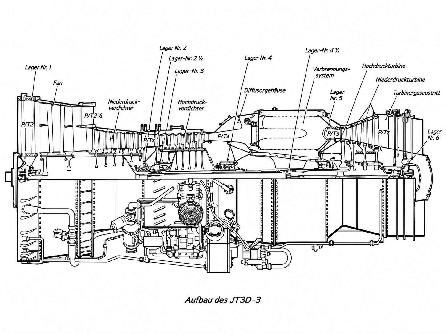
The bearing arrangement is described in unusual detail in the training material. The N1 system is supported by bearings 1, 2, 4 1/2 and 6. The N2 system is supported by bearings 3, 4 and 5. Bearing 2 1/2 carries a sealing ring and is not functionally assigned directly to either rotor. Bearings 2 and 4 are double ball bearings and carry major axial loads. Bearing 4 1/2 supports the two concentric rotor shafts relative to one another and therefore rotates at the differential speed between the two shafts.
The LTS also explains why the bearings must carry more than radial loads. The compressor pressure rise produces a resultant axial force directed forward, while the turbine is loaded aft by the pressure drop and blade forces. The compressor resultant is larger and must be absorbed by the ball bearings. At the same time, the design must allow for thermal changes in shaft length.
Another important point is the accessory drive. A bevel gear is fitted to the high-pressure rotor behind bearing 4. A towershaft drives the main accessory gearbox. Numerous accessories are therefore mechanically dependent directly on the N2 system. This coupling is fundamental to understanding the engine: N2 is not merely a compressor speed indication; through the gearbox it drives several accessories essential for engine operation.
Accessory Drives and Dependence on N1/N2
The training material explicitly separates the accessory drives according to whether they depend on N1 or N2. A separate accessory drive is located at the front of the N1 system. It drives the N1 tachometer generator and the scavenge pump for bearing 1; another scavenge pump for bearing 6 is driven at the rear of the N1 rotor through a spur-gear reduction. This arrangement explains why certain scavenge functions follow low-pressure rotor speed directly.
The considerably larger main accessory gearbox is driven by the N2 system. It is mounted on the diffuser case and is driven through a bevel gear behind bearing 4, a plug-in shaft or towershaft passing through a diffuser-case strut, and another bevel-gear stage in the gearbox. According to the LTS, the main gearbox carries the engine-driven fuel pump, fuel control unit, constant-speed drive and generator, starter, N2 tachometer generator, hydraulic pump, pressure oil pump, main scavenge pump and a centrifugal blower. The hydraulic pump is fitted only to the inboard engines.
This arrangement is particularly important for understanding starting, idle operation and rundown. As long as N2 is not rotating, the mechanically coupled pumps and control components are not operating at normal speed. During starting, the starter initially drives the N2 system through the gearbox train. As N2 rises, the fuel and oil pumps begin to build their operating pressures. After shutdown, their supply capability decreases again with rotor speed. The LTS drawing of the main accessory gearbox makes this mechanical relationship very clear: the fuel pump, FCU, starter, generator drive and oil pumps are not isolated systems, but are mounted on a common gearbox driven by N2.
This creates a clear hierarchy inside the engine. N2 is the mechanical power source for most accessory functions; N1 is primarily the fan/low-pressure spool with its own speed-sensing and scavenge functions. This distinction also helps when interpreting failures: a problem in the N2 drive can simultaneously affect fuel control, lubrication, generator drive or hydraulic supply, while a purely N1-related problem has different consequences.
Airflow, Compression and Combustion
The JT3D airflow path is defined by the division into fan, low-pressure and high-pressure sections. After entering the engine, the fan accelerates and compresses the entire captured airflow. In the fan discharge case the flow is split. The outer portion forms the fan or bypass stream; the inner portion enters the six-stage low-pressure compressor. Downstream is the compressor intermediate case. It carries structural loads and several bearings and, together with the high-pressure compressor case, forms an annular chamber containing P3 air. This annular chamber becomes central to the surge bleed system.
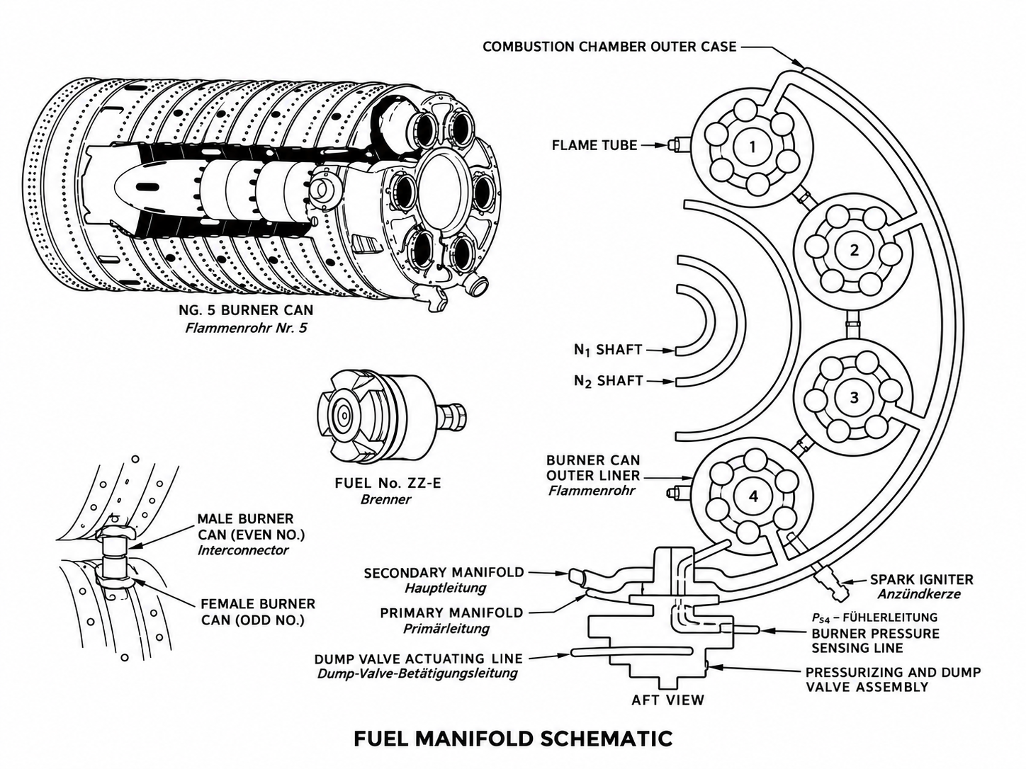
The seven-stage high-pressure compressor increases the pressure further. The air then enters the diffuser and combustion section. The combustion system consists of an annular outer case containing eight interconnected flame tubes. Viewed in the direction of flight, the flame tubes are numbered clockwise; Nos. 1 and 8 are located next to each other at the top. According to the LTS, each flame tube contains six burners with coaxially arranged primary and main atomizers. At low fuel flow, fuel can therefore initially be supplied through the primary circuit, with the secondary stage added at higher flow.
The hot gases first drive the single-stage high-pressure turbine. It supplies the power for the N2 rotor, including the high-pressure compressor and the accessories coupled to it. The gases then pass through the three-stage low-pressure turbine. This turbine extracts additional energy and drives the low-pressure compressor and fan through the long inner shaft. This staged energy extraction is part of the fan concept: core-jet velocity is limited while sufficient shaft power remains available to produce the high fan mass flow.
Lubrication System
The JT3D-3 uses a dry-sump pressure-circulation lubrication system. The oil is therefore not collected in a large sump underneath the engine, but is carried in a separate tank and continuously circulated by pressure and scavenge pumps. The LTS specifies one pressure oil pump and a total of five scavenge pumps. Because the engine uses rolling-element bearings and does not contain highly loaded gear trains in the main gas path, a comparatively low-viscosity synthetic oil at moderate pressure is sufficient for lubrication; however, a high circulation rate is necessary to cool the bearings.
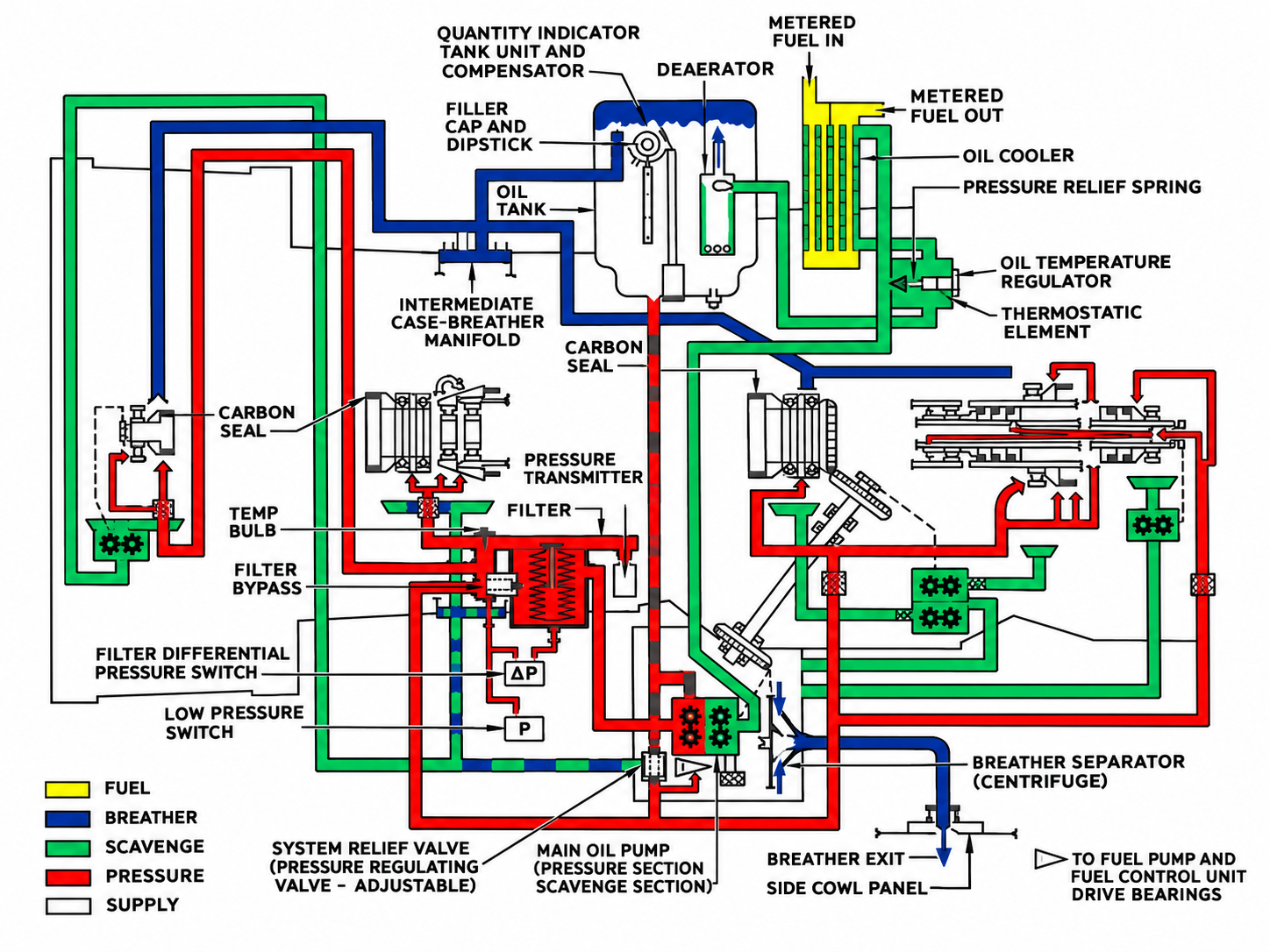
From the oil tank, oil flows to the pressure oil pump in the main accessory gearbox. It then passes through a pressure oil filter with a bypass valve. An adjustable oil pressure relief valve limits maximum operating pressure. The main pressure line branches to the individual lubrication points. Strainers are installed immediately upstream of the oil jets; in particularly hot areas, additional “last chance filters” are fitted to protect the jets from deposits or carbonized oil products.
After lubrication, the oil collects in the bearing sumps. Scavenge pumps remove it and return it through scavenge lines to the main return system. The oil then passes through the oil cooler. A notable feature is its connection with the fuel system: high-pressure fuel from the fuel-control area serves as the cooling medium. Heat is therefore transferred from the oil into the fuel. The cooled oil then returns to the tank, where air separation is provided.
The LTS therefore treats the oil system not as a minor auxiliary function, but as a combined lubrication, cooling, cleaning and preservation system. Oil temperature, oil pressure and oil quantity are the principal monitoring parameters, supplemented by filter condition and pressure-switch indications. The schematic drawing makes it particularly clear that the oil is distributed to several widely separated bearing locations and then collected again through separate scavenge paths.
Cooling and Sealing Air
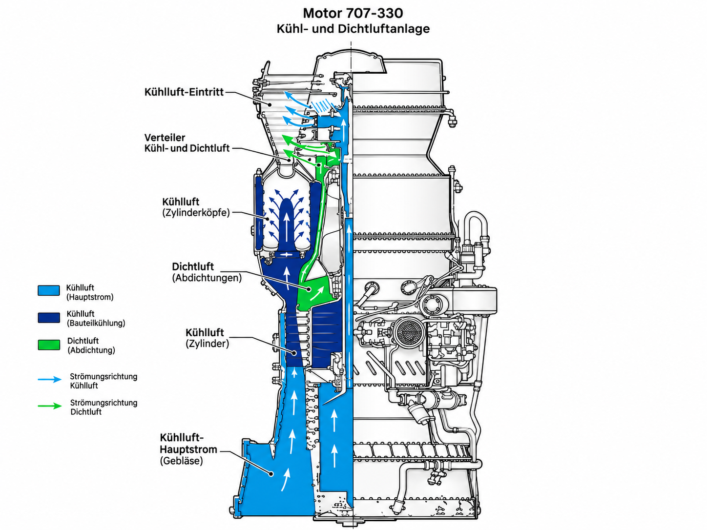
In addition to the main gas path, the JT3D contains an extensive internal network of cooling and sealing air. The LTS emphasizes three tasks: cooling internal components, particularly in the turbine area; pressurizing bearing seals; and, in part, relieving axial bearing loads. Air is tapped from different compressor stages and routed deliberately through cavities, rotor shafts and sealing areas.
A significant portion is taken from the low-pressure compressor discharge as P3 air. This air pressurizes sealing areas around the forward bearings and partly enters the inside of the low-pressure rotor. From there it can be routed through the low-pressure rotor shaft into the turbine region. It provides cooling and at the same time acts on bearing seals. P3 air also fills the annular chamber between the compressor intermediate case and the high-pressure compressor case.
Additional air is taken from a stage of the high-pressure compressor and routed into the interior of the high-pressure rotor. The pressure distribution at the rotor hubs is used deliberately to pressurize seals and influence certain axial loads. At the high-pressure compressor discharge, additional air is tapped through restrictions for particularly hot or pressure-critical areas.
The coloured LTS drawing is particularly useful for understanding this system. It shows that “bleed air” inside the engine does not mean only the familiar external pneumatic supply. A substantial portion of compressor air is used internally as the working medium for sealing, cooling and force balancing. Changes in compressor pressures therefore affect several internal functions directly. Bearing sealing, oil control and rotor loading are structurally closely linked to the internal air system.
Engine Fuel System and Fuel Flow
The engine-side fuel system supplies the combustion system with fuel at the required pressure and in the required quantity. The LTS clearly distinguishes between the primary aircraft fuel system and the secondary engine-mounted fuel system. The major components include the engine-driven fuel pump, fuel heater, main filter, fuel control unit, pressurizing-and-dump valve, and the burner manifolds.
Fuel supplied by the tank boost pumps first reaches the first stage of the engine-driven fuel pump. This two-stage gear pump has a boost stage and a high-pressure stage. Because the boost-stage gears are wider, that stage delivers a greater volume than the high-pressure stage. A pressure-regulating valve maintains its discharge pressure approximately 40 psi above tank-pump pressure. This pressure increase is important to prevent vapour formation during the subsequent fuel-heating process.
After the first pump stage, the fuel passes through the heater and then the filter. The filter has a bypass valve and differential-pressure monitoring for developing icing or increasing blockage. The fuel then returns to the engine-driven pump and is delivered by the high-pressure stage to the fuel control unit. According to the training material, a high-pressure limiting valve limits pump discharge pressure to a maximum of 1,050 psi. If the boost stage fails, a bypass can feed the high-pressure stage directly with tank-pump pressure; the LTS specifies a minimum of 5 psi. In this failure condition, normal fuel heating and filtering are no longer available.
Only the quantity actually required by the combustion system is released by the fuel control unit. Excess high-pressure fuel is returned to the inlet side of the high-pressure pump stage. Metered fuel then passes through the fuel/oil cooler and reaches the pressurizing-and-dump valve. From there it is distributed to the primary and secondary manifolds and finally to the burners.
Pressurizing-and-Dump Valve and Burners
The pressurizing-and-dump valve links fuel metering with the actual injection system. At low speed and low fuel flow, the secondary manifold remains closed. All metered fuel is routed through the primary manifold to the smaller primary atomizers. This keeps pressure high enough for satisfactory atomization even when the total fuel flow is small.
As fuel flow rises, pressure in the primary manifold also rises. The LTS gives approximately 250 psi as the opening pressure of the pressurizing valve. Above this pressure, the spring-loaded valve opens and also supplies the secondary manifold. Fuel then reaches the larger atomizers as well. When power is reduced, pressure decreases again; the spring closes the secondary path and injection returns to the primary side only.
The second function of the unit is the dump valve. Its main purpose is to prevent burner dribble after shutdown. During normal operation, fuel pressure holds the dump valve closed. When the FCU shuts off the fuel supply, control pressure falls, the dump valve opens, and the fuel remaining in the primary manifold can drain into the drain tank.
The LTS burner drawing illustrates the distribution clearly. Primary and secondary manifolds run around the annular combustion system, with lines branching from them to the individual burners. The drawing also shows the Ps4 pressure sensing line and the connection to the pressurizing-and-dump valve. It therefore demonstrates how closely combustion pressure, fuel distribution and fuel control are interconnected: Ps4 is not merely an indication value, but a major input signal to the FCU.
Hydromechanical Fuel Control Unit
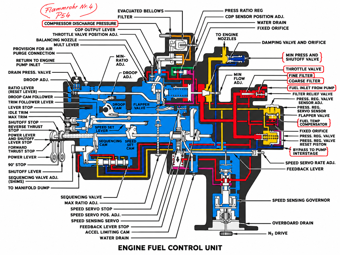
The central control element of the JT3D-3 is the hydromechanical fuel control unit. It is mounted on the main accessory gearbox and is driven by the high-pressure rotor system. According to the LTS, it processes three principal inputs: thrust-lever position, combustion or Ps4 pressure, and the N2 signal. Thrust-lever position represents the requested engine power. Ps4 informs the unit about changes in airflow and is used for acceleration and altitude corrections. N2 is sensed by a governor and is used, among other functions, to limit acceleration and to provide T7 temperature correction.
Actual fuel metering takes place at the variable opening of the throttle valve (T.V.). The pump intentionally supplies more fuel than the engine requires. A pressure-regulator valve and a 40-psi spring maintain an approximately constant differential pressure of about 40 psi across the throttle valve. When the T.V. opening is increased, the differential pressure initially falls; the regulator then reduces bypass flow until total flow has increased enough to restore the 40-psi differential. When the valve closes, the process occurs in the opposite direction. With an essentially constant differential pressure, T.V. position therefore directly determines the metered fuel flow.
The FCU mechanical computing mechanism consists of cams, levers, springs, servos and pressure bellows. When the thrust lever is advanced, the power lever moves the speed-set cam. Through the speed-set lever, droop lever, droop cam, ratio lever and the Ps4 signal, the throttle-valve servo is repositioned. As airflow increases during acceleration, Ps4 also rises and the control unit increases fuel flow accordingly.
The N2 governor prevents a large thrust-lever movement from producing an uncontrolled fuel excess. Flyweights, a pilot valve, servo piston and acceleration-limiting cam alter the permissible fuel-air-ratio schedule. The LTS illustrates acceleration from idle to full power as movement along a “max acceleration line”, “droop line” and “steady state line”. The acceleration-limiting cam restricts enrichment so that the surge region is avoided. The FCU is therefore a purely hydromechanical control system that combines several physical feedback signals to maintain stable engine operation.
Compressor Surge Bleed System
The compressor surge bleed system is a direct consequence of the two-spool architecture. At low rotational speeds, the N1 and N2 compressors have different flow characteristics. According to the LTS, up to approximately 80% N2 the low-pressure compressor delivers more air than the high-pressure compressor can accept. Air can therefore accumulate between the two compressors. Without relief, the operating point would move toward compressor instability or surge.
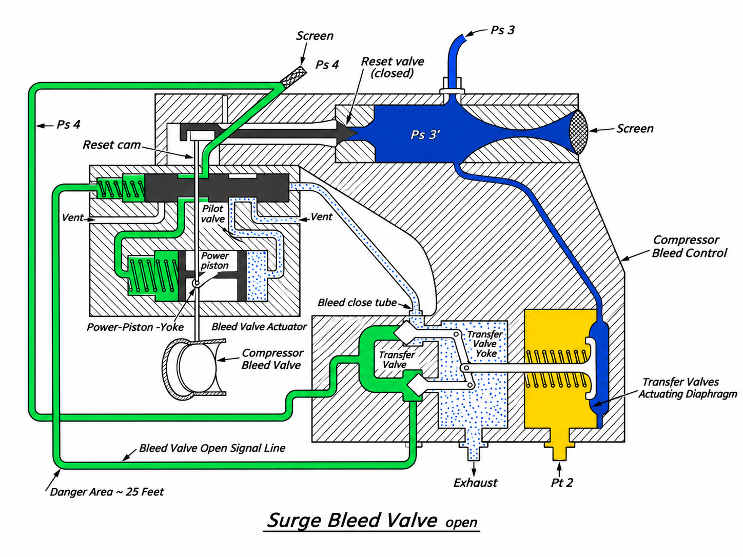
The solution is the surge bleed valve mounted on the compressor intermediate case. It is connected to the P3 annular chamber and can discharge excess low-pressure-compressor air to atmosphere. At low speed the valve is open. As rotational speed increases, the flow capacities of the two compressors approach one another. At the intersection identified in the training material as the “design point”, further bleeding is no longer required.
Control is entirely pneumatic-mechanical. Pt2 at the fan inlet and Ps3 in the compressor-intermediate region are used as control quantities. The Pt2-to-Ps3 relationship is used as a measure of the low-pressure-compressor pressure ratio. Ps4 air from the diffuser case, by contrast, serves as the actual actuating air. The regulator section contains a venturi, actuating diaphragm and transfer valve. The actuator section contains the reset valve, pilot valve, power piston and the compressor bleed valve itself.
At a low compressor pressure ratio, the transfer-valve position routes Ps4 air to the pilot valve and power piston in such a way that the bleed valve opens. Excess P3 air can then escape. As the compressor pressure ratio increases, diaphragm regulation shifts, the pneumatic actuation is reversed and the valve closes. The reset valve protects the regulator diaphragm against the pressure shocks generated during the closing process.
This system illustrates the JT3D design philosophy particularly well: many functions are not produced by electronic controllers, but by pressure relationships, spring forces, diaphragms and servo pistons. The surge bleed valve position is therefore not simply an arbitrary “open” or “closed” command; it is the result of the current compressor operating condition.

Overall System View
The Lufthansa material presents the JT3D-3 as a closely coupled mechanical, pneumatic and hydraulic system. At its core are two independent rotors whose speeds and flow capacities influence one another without being rigidly mechanically coupled. Through its compressor, the N2 system supplies the high pressure required for combustion and at the same time drives the accessories through the towershaft. The N1 system converts a large part of turbine power into fan and low-pressure-compressor work and thereby produces the additional outer thrust stream.
Fuel and air control interact directly. The fuel control unit responds to thrust-lever position, Ps4 and N2 and meters fuel through a hydromechanical servo system. At the same time, the surge bleed system ensures that the two compressors can operate together during low-speed operation and acceleration without entering an unstable region. The oil system is mechanically tied to the accessory drives and thermally linked to the fuel system because fuel serves as the cooling medium in the fuel/oil heat exchanger. Cooling and sealing air connects compressor pressure, bearing sealing, rotor load balancing and turbine cooling.
These interconnections are the most important message of the LTS material. The JT3D-3 cannot usefully be understood as a collection of independent indications. N1, N2, fuel flow, Ps4, oil condition, compressor bleed and internal air routing are different visible effects of the same thermodynamic and mechanical operating state. The Technical School drawings are therefore especially valuable: they show not only individual components, but also the routes taken by air, fuel and oil and the feedback mechanisms by which the engine stabilizes itself.
Illustration Note
The diagrams used in this article have been newly redrawn for presentation on 707jet.com. They are based on the technical relationships and layouts shown in the 1965 training material, but the original document frames, branding and page furniture have deliberately not been reproduced. The historical training documents remain the technical source for the accompanying text.
Source and Figure References
• Lufthansa Technical School: Engine 707-330, Chapter 72-2 General Introduction, August 1965.
• Lufthansa Technical School: Engine 707-330, Chapter 72-3 Construction and Accessory Drives, August 1965.
• Lufthansa Technical School: Engine 707-330, Chapter 72-4 Lubrication System, August 1965.
• Lufthansa Technical School: Engine 707-330, Chapter 72-5 Cooling and Sealing Air System, August 1965.
• Lufthansa Technical School: Engine 707-330, Chapter 73-1 Engine Fuel System, August 1965.
• Lufthansa Technical School: Engine 707-330, Chapter 75-3 Compressor Surge Bleed System, August 1965.